Internal cross-flow type tobacco drying machine
A drying machine and tobacco technology, which is applied in the fields of tobacco, tobacco preparation, and tobacco processing, can solve the problems of slow drying speed, long drying time, and reduced work efficiency, and achieve reduced processing intensity, reduced equipment volume, and improved filling. The effect of recharging
- Summary
- Abstract
- Description
- Claims
- Application Information
AI Technical Summary
Problems solved by technology
Method used
Image

Examples
Embodiment 1
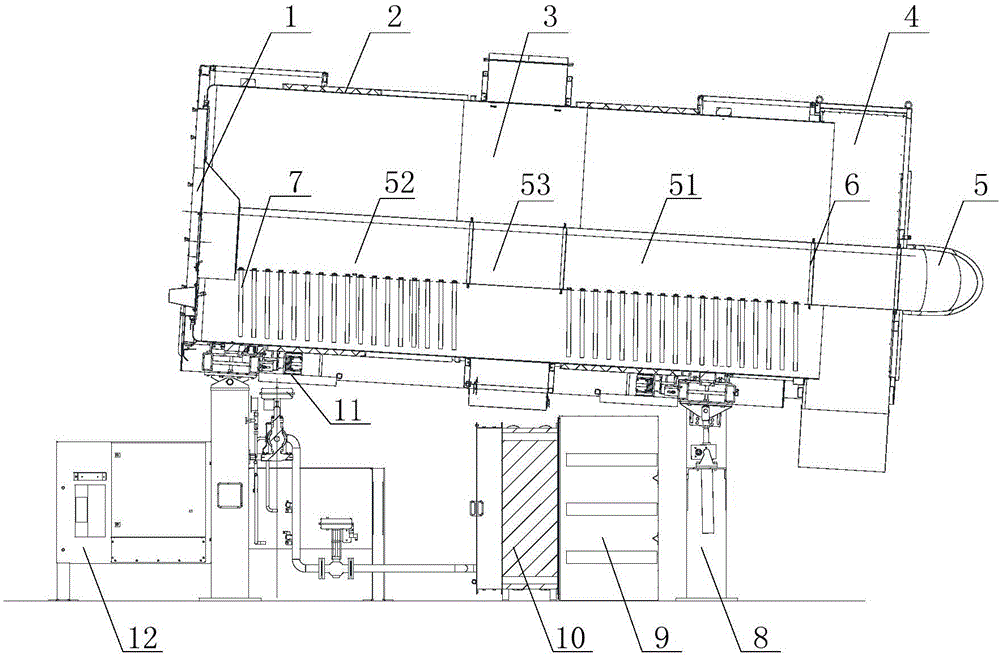
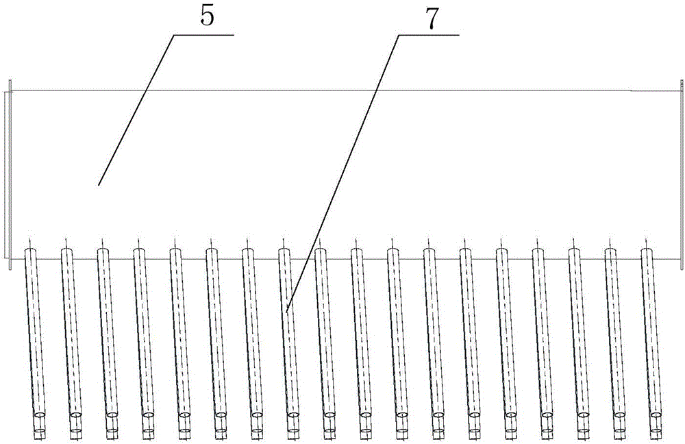
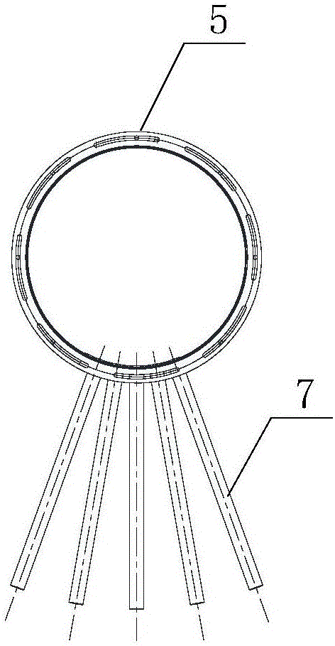
[0034] like figure 1 As shown, an internal through-flow tobacco dryer described in this embodiment includes a cylinder body 2, a feed end 1 and a discharge end 4, and the cylinder body 2 is rotatably arranged at the feed end 1 and the discharge end between 4. The tobacco material enters the interior of the cylinder body 2 from the feed end 1 and flows out from the discharge end 4 after being dried. Inside the cylinder body 2 is provided a central tube 5 for drying the tobacco, the central tube 5 runs through the cylinder body 2, and its two ends are fixedly installed on the feed end 1 and the discharge end 4 respectively. The discharge end 4 is provided with a dry gas inlet, and the dry gas enters the central tube 5 through the dry gas inlet. The lower part of the central tube 5 is evenly distributed with air that can discharge the drying gas and act on the tobacco material that is always at the bottom of the cylinder body 2 .
[0035] The control system 12 for controlling ...
Embodiment 2
[0040] like figure 1 As shown, an internal through-flow tobacco dryer described in this embodiment is mainly composed of a cylinder body 2, a feed end 1, a discharge end 4, a central pipe 5, a branch pipe 7, a moisture removal device 3, and a control system 12. Drive device 11, heat exchanger 10, fan 9 and legs 8. Wherein, the cylinder body 2 is located between the feed end 1 and the discharge end 4 and is driven by the drive device 11 to rotate, and the central pipe 5 and the branch pipe 7 do not rotate with the cylinder body 2 . The rotation of the cylinder body 2 enables the tobacco material at the bottom of the cylinder body 2 to fully contact with the drying gas discharged from the branch pipe 7, so as to achieve the purpose of drying more fully.
[0041] In this embodiment, the central pipe 5 runs through the inside of the cylinder body 2 and includes a first central pipe 51, a connecting pipe 53 and a second central pipe 52, and the two ends of the connecting pipe 53 a...
PUM
 Abstract
Description
Claims
Application Information
 - Generate Ideas
- Intellectual Property
- Life Sciences
- Materials
- Tech Scout
- Unparalleled Data Quality
- Higher Quality Content
- 60% Fewer Hallucinations
Browse by: Latest US Patents, China's latest patents, Technical Efficacy Thesaurus, Application Domain, Technology Topic, Popular Technical Reports.
© 2025 PatSnap. All rights reserved.Legal|Privacy policy|Modern Slavery Act Transparency Statement|Sitemap|About US| Contact US: help@patsnap.com