Novel vertical deep ocean pipe with slug flow subduction

A deep-sea riser and slug flow technology, which is applied in pipeline systems, mechanical equipment, gas/liquid distribution and storage, etc., can solve problems such as blocked pipelines, increased wellhead back pressure, pipeline vibration, etc., and achieve the effect of avoiding damage

Active Publication Date: 2017-02-01
SOUTHWEST PETROLEUM UNIV
View PDF8 Cites 3 Cited by
  • Summary
  • Abstract
  • Description
  • Claims
  • Application Information

AI Technical Summary

Problems solved by technology

[0010] After a large number of domestic and foreign literature surveys, it was found that foreign researchers in the open literature mainly conducted mechanical analysis on flexible risers, and did not design related flexible riser structures to reduce slug flow. Most domestic researchers stayed at the theoretical research stage and had no relevant Reporting of Tangible Research Results
[0011] (2) Slug flow hazard in standpipe
[0013] 1) The slug flow sharply increases the pressure drop of the pipeline, which leads to an increase in the back pressure of the wellhead and reduces the production of oil and gas wells;
[0014] 2) Gas and liquid flow out alternately at the outlet of the pipeline, causing the downstream separator to overflow or stop flow;
[0015] 3) Severe pressure fluctuations will aggravate the corrosion of the standpipe wall and cause pipeline vibration;
[0017] 5) The gas produces Joule-Thomson temperature drop effect during the eruption process, which leads to the formation of wax deposition and hydrate on the pipe wall, thereby blocking the pipe

Method used


Image

  • Novel vertical deep ocean pipe with slug flow subduction
  • Novel vertical deep ocean pipe with slug flow subduction
  • Novel vertical deep ocean pipe with slug flow subduction

Examples


Embodiment

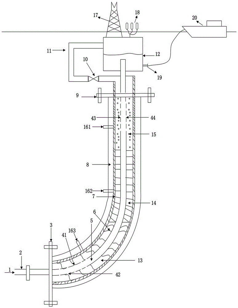
[0051] In this example, figure 1It is a schematic diagram of a new deep-sea riser structure with slug flow reduction, including oil-gas-water three-phase medium 1, production pipeline 2, blind flange 3, first communication hole 41, second communication hole 42, third communication hole 43, Fourth communication hole 44, inner pipe 5, outer pipe 6, insulation layer 7, heat insulation layer 8, connector 9, gas volume regulating valve 10, gas injection pipeline 11, floating separator 12, water phase 13, oil phase 14, Gas phase 15 , first pressure sensor 161 , second pressure sensor 162 , third pressure sensor 163 , flare tower 17 , buoy 18 , liquid phase outlet 19 , and oil storage vessel 20 .

[0052] The production pipeline 2 is connected to the inner pipe 5 through the blind flange 3, the oil-gas-water three-phase medium 1 enters the inner pipe 5 through the production pipeline 2, and the inner pipe 5 is connected to the floating separator 12 through the connector 9, The outer...


PUM


Abstract

The invention relates to a novel vertical deep ocean pipe with slug flow subduction. The novel vertical deep ocean pipe with slug flow subduction integrates multiple functions such as slug flow trapping, gas lifting of the bottom part of the vertical pipe, gas-liquid separating of the top part of the vertical pipe, and online monitoring of pressure in the vertical pipe into a whole; an inner pipe and an outer pipe of the vertical pipe are designed; a certain number of communicating holes with definite size are formed in the bottom part and the top part of an inner pipe wall, so that pressure balance of the inner pipe and the outer pipe is kept; one-way floating valves are designed on the communicating hole parts in the top part of the inner pipe wall, so that a fluid of the outer pipe one-way enters the inner pipe; a gas lifting system is designed, and gas enters the inner pipe through communicating holes on an outer pipe wall, so that the density, the speed and the length of a slug flow are changed, and the slug flow subduction under different working conditions is realized; a floating type separator on the top part of the vertical pipe is designed, so that an oil-gas separation effect is produced; and a pressure on-line monitoring system is designed, and pressure sensors are arranged on the bottom part, the middle part and the upper part of the vertical pipe, so that the pressure change in the vertical pipe is monitored in real time, and a basis is provided for gas lifting gas flow regulation.

Description

technical field [0001] The invention relates to a novel deep-sea riser with slug flow reduction, belonging to the technical field of marine gathering and transportation. Background technique [0002] In the process of offshore oil and gas exploitation, the riser is used to connect the mixed transportation pipeline on the seabed with the offshore floating production and storage vessel. The deep-sea riser system has a large elevation difference, which is prone to slug flow. [0003] (1) Research status of deep sea flexible risers [0004] Deep-sea flexible risers are the key link between subsea production systems and floating devices. There are two types of flexible pipes currently used: bonded flexible pipes and non-bonded flexible pipes. Deep-sea risers mostly use non-bonded flexible risers. The main structure of the flexible riser from the inner wall to the outer wall is as follows: stainless steel lining pipe, internal pressure protection layer, internal lock pressure lay...

Claims


Application Information

Patent Timeline
Patent Type & Authority Applications(China)
IPC IPC(8): F17D1/00F17D1/20F17D3/01
CPCF17D1/005F17D1/20F17D3/01
Inventor 刘武邹宇谷雪琴
Owner SOUTHWEST PETROLEUM UNIV
Why Eureka
Try Eureka