Fixtures for glass mold cavity spray welding

A glass mold and tooling technology, applied in the field of tooling and fixtures, can solve the problems of many action transmission links, large mold clamping frame, and high operating intensity, so as to ensure stability and reliability of action, and reduce action transmission links. , the effect of avoiding accidents

Active Publication Date: 2017-12-29
CHANGSHU JIANHUA MOLD TECH +1
View PDF17 Cites 2 Cited by
  • Summary
  • Abstract
  • Description
  • Claims
  • Application Information

AI Technical Summary

Problems solved by technology

However, the patent scheme provided by this CN102019496B has the following shortcomings: First, because this patent is used as a transition mechanism between industrial robots and plasma spray welding machines, that is, it needs to be used in conjunction with industrial robots because it cannot turn around itself, so for my country For small and medium-sized glass mold manufacturers with a wide range of areas, it is not only difficult to invest in industrial robots, but also has technical bottlenecks in use and maintenance; second, because it can only reflect the effect of rapid clamping and release of glass molds , so the adaptability to the size of the glass mold is relatively poor; third, the overall structure is still relatively complicated, which makes manufacturing and assembly difficult, and consumes a lot of materials, which is not conducive to saving resources; fourth, although the patent can The spray-welded glass mold exhibits the degree of freedom of rotation as required, but because it is realized by the wrist movement of the robot, it is not given to use an ordinary device to clamp the half-mold of the glass mold under the premise of getting rid of the control of the robot. Enlightenment that the clamping mechanism can rotate freely
[0007] The "rotatable glass mold tool and fixture device" recommended by the invention patent authorization announcement number CN103358077B makes up for the shortcomings of the aforementioned CN102019496B and can objectively fulfill the five technical effects summarized in the technical effect column of the specification, but there are still the following Disadvantages: First, because the glass mold to be spray-welded with the nickel-based alloy layer is clamped on the mold clamping frame in a longitudinal state, not only the mold clamping frame is large in size, but also has a relatively complicated structure. For example, it needs to be equipped with a cylinder as a Power mold back positioning mechanism; second, because it can only be suitable for the mold cavity of the glass mold to carry out longitudinal clamping on the side of the mold back positioning mechanism, so compared with the supine clamping with the glass mold cavity facing upward As far as the installation is concerned, the operator’s operating intensity is much greater (clamping is laborious), and there is still a problem of low safety factor in the longitudinal clamping; the third is that when the rotary drive mechanism of the rotary seat is used to drive the mold clamping frame clockwise or When deflecting the required angle counterclockwise, the rotary seat must be driven by the wall plate fixed to the rotary seat, and then the mold mounting frame must be driven by the rotary seat. Therefore, the rotary seat drive motor of the rotary drive mechanism of the rotary seat is required to have relatively large power, so Not only are there many action transmission links, but it is also not conducive to saving power consumption. Of course, if the rotary base is designed as a frame seat that is separated from the rotary drive mechanism of the rotary base and made static, and the rotary drive mechanism of the rotary base is evolved into a The mold clamping frame drive mechanism directly connected to the clamping frame can undoubtedly make up for this deficiency, that is, it can reduce the power transmission link and save power consumption, but all the aforementioned patents including this CN103358077B None of the literature gives any inspiration for reference; Fourth, due to the large volume of the device and the high center of gravity, it not only increases the occupation of space, but also lacks stability

Method used


Image

  • Fixtures for glass mold cavity spray welding

Examples


Embodiment Construction

[0022] In order to understand the technical essence and beneficial effects of the present invention more clearly, the applicant will describe in detail the following examples, but the descriptions of the examples are not intended to limit the solutions of the present invention. Equivalent transformations that are only formal but not substantive should be regarded as the scope of the technical solution of the present invention.

[0023] In the following descriptions, all concepts related to directionality or orientation of up, down, left, right, front and back are based on figure 1 The current position is a reference, so it cannot be understood as a special limitation on the technical solution provided by the present invention.

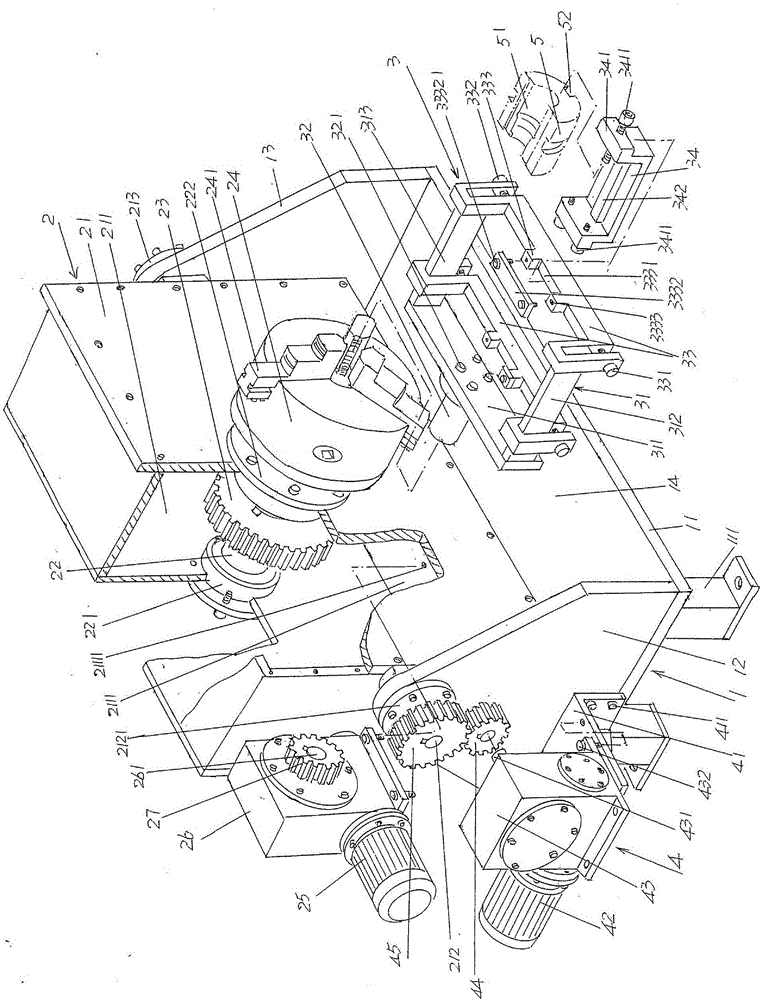
[0024] See figure 1 , shows a frame 1 (also can be referred to as "base", hereinafter the same), this frame 1 is made up of frame bottom plate 11, frame left wall plate 12 and frame right wall plate 13, frame bottom plate 11 Supported by the support ...


PUM


Abstract

The invention relates to a tool clamp for mold cavity spray welding of a glass mold. The tool clamp comprises a rack, a mold horizontal clamping support driving mechanism, a mold horizontal clamping support and a reversing support driving mechanism; the rack is composed of a rack bottom plate, a rack left wallboard and a rack right wallboard, wherein the rack left wallboard is fixed to the left end of the rack bottom plate, the rack right wallboard is fixed to the right end of the rack bottom plate, and a rack cavity is formed in a space between the rack left wallboard and the rack right wallboard; the mold horizontal clamping support driving mechanism is supported between the rack left wallboard and the rack right wallboard; the mold horizontal clamping support is clamped to the mold horizontal clamping support driving mechanism at the position corresponding to the front side of the mold horizontal clamping support driving mechanism; and the reversing support driving mechanism is arranged on the side, back to the rack right wallboard, of the left wallboard and connected with the mold horizontal clamping support driving mechanism. The structure of the mold horizontal clamping support is simplified, and the size is decreased; clamping is convenient and saves labor, the strength of an operator is reduced, so that safety is improved, and accidents are avoided; the motion transmission link is omitted, and the energy-saving effect is shown; and the size is small, the center of gravity is reduced, the space is saved, and the stability and the motion reliability are guaranteed.

Description

technical field [0001] The invention belongs to the technical field of fixtures, in particular to a fixture for glass mold cavity spray welding. Background technique [0002] Glass molds are important equipment for manufacturing glass containers such as various beer bottles, red wine bottles, beverage bottles and even daily cosmetic bottles. In the molding process of glass products, for glass molds with two or more openings, the mold cavity is directly in frequent contact with the molten glass melt, and is subjected to chemical erosion, abrasion and alternating stress of cold and heat of the glass (cold and hot). Alternate thermal stress), and service at a temperature of about 500-800°C, the surface of the cavity, the seam surface and even the end faces at both ends are easily oxidized, and there is an unavoidable impact between the mold parts, which will cause and Not limited to the following damage situations: fatigue damage, mechanical impact damage, oxidation corrosion ...

Claims


Application Information

Patent Timeline
Patent Type & Authority Patents(China)
IPC IPC(8): B23K37/04B23K37/047B23K26/342B23K26/70
CPCB23K26/342B23K26/702B23K37/0435B23K37/047
Inventor 马建华杨继全晏庆宝莫志勇韩志强刘益剑
Owner CHANGSHU JIANHUA MOLD TECH
Why Eureka
Try Eureka