Sewage treatment system of artificial wetland

A sewage treatment system and constructed wetland technology, which is applied in the field of constructed wetland sewage treatment system, can solve the problems of little contribution of hydrolytic acidification pool to the treatment effect, poor sewage treatment effect of wetland unit, and low pollutant removal efficiency, so as to achieve water purification Outstanding effect, convenient management and maintenance, and improved survival rate

Inactive Publication Date: 2017-02-15
SHANGLUO UNIV
View PDF3 Cites 8 Cited by
  • Summary
  • Abstract
  • Description
  • Claims
  • Application Information

AI Technical Summary

Problems solved by technology

[0005] 1. The pre-hydrolytic acidification tank does not contribute much to the treatment effect. Most of the organic matter is removed by the medium interception of the wetland, the adsorption of the roots and the action of microorganisms. The removal rate of the pollutants in the hydrolytic acidification tank itself is not high. The pollutant removal rate of the whole constructed wetland is lower than that of the traditional A / O system (ie aerobic / anaerobic process or anaerobic / aerobic process) and other methods
[0006] 2. The hydrolytic acidification tank often emits acid, smell or produce unpleasant smell
[0007] 3. Because the removal efficiency of pollutants in the hydrolytic acidification tank is not high, the organic matter in the domestic sewage, especially the organic suspended matter (or particulate matter) is likely to cause blockage of the constructed wetland
[0009] 5. The sewage treatment effect of the wetland unit is poor

Method used


Image

  • Sewage treatment system of artificial wetland
  • Sewage treatment system of artificial wetland

Examples


Embodiment Construction

[0024] In order to make the objects and advantages of the present invention clearer, the present invention will be further described in detail below in conjunction with the examples. It should be understood that the specific embodiments described here are only used to explain the present invention, not to limit the present invention.

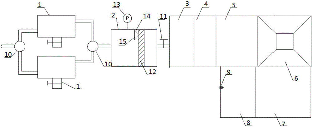
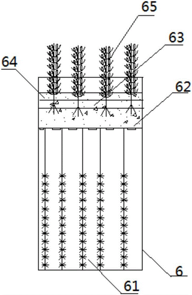
[0025] Such as Figure 1-Figure 2 As shown, the embodiment of the present invention provides a constructed wetland sewage treatment system, which includes two sedimentation tanks 1 arranged in parallel, and the front and back of the two sedimentation tanks 1 are respectively provided with reversing valves, and the bottom of each sedimentation tank is provided with a The slag outlet, the downstream of the sedimentation tank 1 is provided with a grid well 2, an aeration regulating tank 3, a hydrolysis acidification tank 4, a contact oxidation tank 5, a wetland purification tank 6, an aeration wetland purification tank 7 and a disinfection tank 8 t...


PUM

PropertyMeasurementUnit
thicknessaaaaaaaaaa
diameteraaaaaaaaaa
thicknessaaaaaaaaaa

Abstract

The invention discloses a sewage treatment system of an artificial wetland. The sewage treatment system comprises two sedimentation tanks which are arranged in parallel, wherein reversing valves are arranged in front and back of the two sedimentation tanks respectively; a dreg discharging hole is formed in the bottom of each sedimentation tank; a grating well, an aeration adjusting tank, a hydrolytic acidification tank, a contact oxidization tank and a wetland purification tank, an aeration wetland purification tank and a disinfection tank are arranged at the downstream of the sedimentation tanks through pipelines; the grating well is internally provided with a coarse grating and a fine grating in sequence from a water inlet to a water outlet; a pressure sensor and a negative-pressure suction nozzle are arranged at a water inlet side of the fine grating; the negative-pressure suction nozzle is connected onto a retractable rod; the negative-pressure suction nozzle is clung to the fine grating; the grating well is communicated to the aeration adjusting tank through a water inlet pipe; a filter screen is obliquely arranged in the aeration wetland purification tank; a plurality of grades of composite packing wetland regions are arranged above the filter screen; a free falling water height difference is formed between two adjacent grades of composite packing wetland regions. By optimizing a structure and a material, the purification efficiency of sewage is greatly improved and the sewage treatment system is not easy to block.

Description

technical field [0001] The invention relates to the field of sewage treatment, in particular to an artificial wetland sewage treatment system. Background technique [0002] The constructed wetland system is a water treatment system that consumes less power. It uses artificial methods to build a wetland system, and uses media filtration, plant root adsorption, and the action of microorganisms in the media to treat wastewater, especially for domestic sewage. [0003] A traditional constructed wetland system generally includes a hydrolytic acidification unit and a wetland unit. The hydrolytic acidification unit pretreats the wastewater, and converts macromolecular organic matter into small molecular organic matter through hydrolysis, so that it can be more easily degraded by microorganisms in the medium in the wetland unit. In addition, the hydrolytic acidification unit can convert the organic nitrogen in the wastewater into ammonia nitrogen, which is more conducive to the ab...

Claims


Application Information

Patent Timeline
Patent Type & Authority Applications(China)
IPC IPC(8): C02F3/32C02F3/30
CPCC02F3/30C02F3/32C02F2303/14Y02W10/10
Inventor 赵培张孝存
Owner SHANGLUO UNIV
Why Eureka
Try Eureka