Reflector and susceptor assembly for chemical vapor deposition reactor

A susceptor and reflector technology, applied in gaseous chemical plating, metal material coating process, coating and other directions, can solve problems such as reducing useful life

Inactive Publication Date: 2017-02-15
紫石能源有限公司
1 Cites 1 Cited by

AI-Extracted Technical Summary

Problems solved by technology

However, localized overheating along the length of the lamp, due to filam...

Abstract

A reactor for chemical vapor deposition is equipped with an IR radiation compensating susceptor assembly that supports one or more semiconductor substrates above linear IR heater lamps arranged in a parallel array. A set of primary IR radiation reflectors beneath the lamps directs IR radiation back toward the susceptor in a pattern selected to provide uniform IR irradiation of the susceptor assembly to thereby uniformly heat the substrates. Secondary IR shield reflectors may be provided in selected patterns on the underside of the susceptor assembly as a fine tuning measure to direct IR radiation away from the assembly in a controlled pattern. The combined IR radiation reflectors have an IR signature that compensates for any non-uniform heating profile created by the linear IR heater lamp array. The heating profile of the lamp array might also be tailored in order to reduce the amount of compensation required to be supplied by the IR reflectors.

Application Domain

Chemical vapor deposition coatingOhmic-resistance heating devices

Technology Topic

PhysicsSemiconductor +5

Image

  • Reflector and susceptor assembly for chemical vapor deposition reactor
  • Reflector and susceptor assembly for chemical vapor deposition reactor
  • Reflector and susceptor assembly for chemical vapor deposition reactor

Examples

  • Experimental program(1)

Example Embodiment

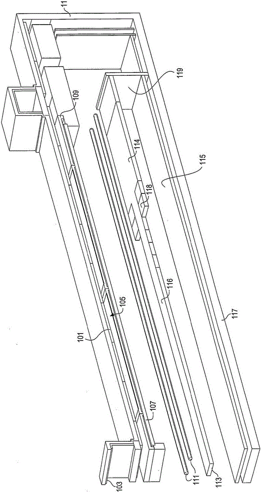
[0019] The present invention can be applied to a variety of possible reactors where the uniformity of the temperature rise of the substrate is important or highly desired, especially for producing uniform deposition of materials on such substrates. Although the example given herein is a CVD cold-wall reactor in which the heater has one or more line lamp arrays, other similar reactors are considered to be included in the present invention. The improvement herein provides a processing kit for a susceptor for radiant heating, in which one or more IR reflector elements compensate for the non-uniform heating profile from any type of heater employed in the reactor.
[0020] in figure 1 , A part of the cold wall reactor 11 supports the nozzle diffuser 101 and the nozzle assembly above the gas supply manifold 103. One end of the reactor 11 can be seen on the right side of the figure, while the left-hand side of the figure corresponds to the central part of the reactor 11, and the opposite end of the reactor is not visible beyond the left side of the figure. (Because the reactor 11 exhibits a mirror image as a whole, only half of the reactor is shown without losing important things.) A shower head not shown guides the reaction gas to the susceptor 105, and the susceptor 105 sets the substrate (not shown) ). The substrate is preferably a rectangle with X and Y axes, one of which is aligned in the direction of travel through the reactor. Below the susceptor 105 is a transparent carrier 107 supported by a bracket 109. The linear tube lamp 111 electrically generates infrared radiation. The linear tube lamp 111 is parallel and spaced apart from each other in a plane on the reflector structure 113. The reflector structure 113 forms the primary IR reflector of the present invention. The longitudinal direction of the lamp 111 is aligned with the X or Y axis of the substrate. The X or Y axis may be in the direction of travel or perpendicular to the direction of travel. Although the IR reflector structure 113 is used to more evenly distribute the heating of the susceptor and the wafer substrate located thereon, the heating lamp 111 itself can be configured to reduce the amount of heat compensation that needs to be provided by the reflector structure 113. For example, the lights 111 at the edges of the susceptor can provide a higher output power level because there are fewer lights at the edges that help the susceptor to heat up compared to the center of the susceptor. Likewise, the lamp 111 may have a non-uniform output along its length, so that the center of the lamp has a lower energy output than the end of the lamp. Nevertheless, the present invention will also be effective for lamps with uniform output or lamp arrays all having the same output, but these lamps or lamp arrays have a greater thermal compensation than required by the IR reflector.
[0021] The primary IR reflector 113 is a reflector under the IR lamp, which may be formed of a conventional IR reflective material such as opaque quartz, but unconventionally provides a spatial IR reflection pattern that compensates for the lamp 111 having a wider end 114, for example The non-uniform irradiation of the susceptor 105 by itself. The central portion 116 of the IR reflector 113 may be thinner as seen here or not present at all. The relative length of the wider end portion 114 and the thinner (or non-existent) central portion 116 can be adjusted one by one by providing a movable section 118 as appropriate. The wider end portion 114 reflects more IR radiation from the lamp 113 towards the susceptor 105 at the end of the reactor 11, thereby compensating for the overall lower IR radiation from the lamp in those end regions of the reactor . The narrower central portion 116 reflects IR radiation. At the same time, this provides the IR reflector structure 113 with a specified IR reflection profile that compensates for the common lamp output, resulting in more uniform heating of the susceptor 105 and the substrate thereon.
[0022] In addition to (or in addition) by changing the width, an alternative way to provide the IR reflection pattern is to change the IR reflection characteristics of the reflector structure 113. For example, if the reflective material of the reflector 113 is a copper-gold-plated structure, replacing the gold-plated with a graphite coating in the central area 116 of the reflector will reduce the IR reflectivity in these areas. The gold-plated end region 114 will have a higher IR reflectivity.
[0023] Optionally, the secondary IR reflector ( Figure 5 It is better visible in) towards the IR lamp 111 mounted on the carrier 107 in the container below the susceptor 105 in order to reflect the heat radiation away from the susceptor 105 so as to further distribute the heat more evenly and avoid hot spots. The secondary IR reflector structure can be a thin refractory metal foil, which can be stamped, chemically etched, laser cut or otherwise processed to produce a precise silhouette profile. The polishing foil preferably composed of molybdenum has a known infrared reflectivity at elevated temperatures, which can be mathematically modeled. Any such secondary reflector should have a low thermal mass to minimize the deceleration of substrate heating. They are as useful as inserts for fine-tuning the IR profile, as needed, for example, according to lamp life.
[0024] The main heat transfer from lamp 111 to susceptor 105 is through IR radiation (direct radiation and radiation reflected by the primary reflector structure). The reflection profile is the profile that guides the radiation away from the housing wall and passes it through the transparent carrier 107 toward the susceptor 105.
[0025] Below the primary reflector structure 113 may be an inner chamber lining 115. The inner chamber lining 115 may be graphite or ceramic for supporting the reflector structure 113 by the bracket 119 so that the reflector structure is only a few millimeters away from the lamp 111 , Resulting in the temperature of the reflector structure 113 near 1100 degrees Celsius. The outer chamber wall 117 is a part of the cold wall reactor structure 11 and provides support for the reflector structure at the opposite end thereof, so that the reflector structure at the opposite outer end is supported by the bracket.
[0026] 2A and 2B, the susceptor heating distribution assembly 127 has a graphite susceptor 105, which is one of four similar susceptors in a 2×2 array in the ceramic holder. Each susceptor here carries a substrate (not shown) in a shallow recess for the deposition of reactive gas in the reactor. The 2×2 array of four susceptors is located below the 2×2 array of nozzles, which is also not shown. Each array of 4 susceptors is supported by a transparent quartz plate 129. The four susceptors are surrounded by a graphite frame 125, and the graphite frame 125 is also supported by a quartz plate 129. The quartz carrier plate allows infrared radiation to pass through the carrier plate to the susceptor, and the infrared radiation in the susceptor is easily absorbed. The graphite frame 125 is more capable of absorbing infrared radiation than the susceptor structure because the reflector structure is patterned to guide heat away from the susceptor in a more preferred manner, with reduced heat to the boundary 125, and even towards the wall. Less calories. The radiation distribution pattern provided by the reflector structure can be modeled on a global basis of the entire array of susceptors 105 or on a susceptor-by-susceptor basis.
[0027] in image 3 The graphite frame 125 surrounding the susceptors 105 and 106 can be seen. Each susceptor has a container or recess that carries a wafer substrate not shown, on which a high-temperature MOCVD reaction is realized. The substrate is heated by conduction from the associated susceptor, and the substrate is intended to be at a high temperature required for the CVD reaction and compared to the surrounding structure. The quartz sheet 129 provides support for the two susceptors 105 and 106 and the graphite boundary 125. It should be noted that only a small part of the quartz plate 129 and the graphite boundary 125 are in contact with the ceramic holder 127.
[0028] Figure 4 In this, the graphite susceptor 105 is shown as having a caulking container in the lower surface relative to the quartz plate 129 on which the susceptor is located. The container has a size for optionally housing the reflective elongated metal strips 112, 114 of the secondary IR reflector structure, which may have a longitudinal direction parallel to the axis of the tubular heater lamp. Several parallel, spaced apart strips are provided on the underside of the susceptor to reflect and thereby shield the infrared light from the heating lamp, so that the desired uniform heating pattern in a set of susceptors can be fine-tuned. The susceptor is heated strongly by the lamp, which may have some thermal roll-off in the surrounding graphite boundary and further roll-off in the direction of the holder toward the reactor wall, which is adjacent to the wall to such an extent that it is under the lamp The primary IR reflector may not be able to fully compensate with its own spatial reflection pattern. Therefore, in order to assist the primary reflector and to fine-tune the IR radiation to more fully ensure uniform heating of the susceptor, the reflector strip at the center of the susceptor array will be slightly wider, that is, greater regional reflectivity, because the heat is in all areas. The reflective strips that will be transferred away in the direction and further away from the center of the susceptor array are slightly narrower, that is, smaller reflectivity. Because of the limitation of the graphite boundary contacting the insulating holder, heat is transferred in fewer directions open.
[0029] reference Figure 5 , Each array of the four susceptors 211, 213, 215 and 217 has a plurality of parallel secondary reflection strips 221 just below the susceptor and above the quartz plate 223. The quartz plate 223 is placed on the parallel infrared tube heating lamp. Above the array, which is not shown, is aligned perpendicular to the parallel reflection bars. The reflective strip is configured to generate uniform heating in the susceptor and less heating at the boundary, which is not shown, and less heat in the insulating ceramic holder 225. reference figure 1 The primary reflector previously discussed but not seen here is placed under the heating lamp to direct the radiation upward to the susceptor, while the secondary reflector strip 221 is placed to reflect the radiation downward away from the susceptor. Generates multiple bounce effects of radiation, providing uniform heat distribution in the susceptor.
[0030] In order to obtain the desired heating pattern in the susceptor 105, the secondary reflector metal strip or disk 107 can be located directly under the susceptor 105, as described below, with its bright reflective surface facing the IR lamp 111 to direct the radiation toward the lamp 111 is drawn back and away from the portion of the susceptor 105, thereby concentrating the heat in a desired area, for example, under the substrate. Again, this secondary reflective strip produces a desired heating profile in the susceptor 105, which tends to cause heat to leave the wall of the reactor 11 and the part of the susceptor support structure where the susceptor is not located.
[0031] The silhouette profile of the secondary IR reflector structure 107 is characterized by the number and size of the openings, wherein the openings are optimized to control radiant heat transfer. The reflector without openings reflects almost all incident radiation, thereby minimizing radiant heat transfer from the IR lamp to the susceptor. In contrast, a reflector with a large total opening area and a small remaining area of ​​reflective material allows almost all incident radiation to be transmitted from the IR lamp to the susceptor.
[0032] The number and size of the openings are adjusted to produce IR reflectivity controlled features or distribution patterns that effectively compensate for the non-uniform heating profile produced by the linear IR heater lamp array. An IR reflector with a small total open area is installed under a substrate that is exposed to above-average radiation from a linear IR heating lamp array (eg, near the middle of the lamp). An IR reflector with a large total open area is installed under the substrate exposed to below-average level of radiation from the linear IR heating lamp array, for example, near the lamp end. The use of a thin refractory metal foil best produces an IF reflector with a small total open area. The reflectivity of these reflectors can be reduced by patterning an array of openings (e.g., circular, square, rectangular, or other geometric shapes) in order to increase the total opening area. The openings can be regularly spaced to reflect the radiation away uniformly, or the openings can be arranged linearly and sequentially to bias the radiation to one side of the substrate. Another alternative embodiment involves arranging individual refractory foil strips of the same or different widths under the susceptor, instead of processing the slits into indivisible foils. The use of refractory metal wires woven into a fine grid (usually 0.005 inch diameter wires or larger diameter wires) optimally produces an IR reflector with a large total open area. The reflectivity of these reflectors can be increased by using larger diameter wires and by weaving tighter grids to reduce the wire spacing. The combination of heater lamp output distribution and bottom IR reflector distribution can produce the desired uniform thermal profile on a global basis or on a chip-by-chip basis.
[0033] The reflective metal foil is in the range of 0.015 to 0.030 inches (approximately 380 to 760 μm) thick, with a preferred thickness of 0.020 inches (500 μm). This bright thin foil has a low thermal mass, which prevents conductive heat transfer from the secondary reflector structure 107 to the substrate and susceptor assembly 105.

PUM

no PUM

Description & Claims & Application Information

We can also present the details of the Description, Claims and Application information to help users get a comprehensive understanding of the technical details of the patent, such as background art, summary of invention, brief description of drawings, description of embodiments, and other original content. On the other hand, users can also determine the specific scope of protection of the technology through the list of claims; as well as understand the changes in the life cycle of the technology with the presentation of the patent timeline. Login to view more.
Why Eureka
Try Eureka