Broadband laser protection method and structure
A laser protection and wide-band technology, applied in the direction of offensive equipment, weapon types, etc., can solve the problems of lack of protective measures, etc., and achieve the effect of reliable preparation method, short processing time and high yield
- Summary
- Abstract
- Description
- Claims
- Application Information
AI Technical Summary
Problems solved by technology
Method used
Image
Examples
preparation example Construction
[0027] A method for preparing a broadband laser protection structure, comprising the steps of:
[0028] (1) The sapphire material is polished first, and it has a very good surface morphology, and the root mean square surface roughness is kept below 3nm. Before preparing the vanadium oxide film on the sapphire material, first use cotton dipped in detergent to gently scrub the dust and particles on the sapphire surface, then ultrasonically vibrate it in acetone and alcohol for 20 min, and then ultrasonically clean the sapphire in deionized water 20 min.
[0029] (2) Use the radio frequency magnetron sputtering method to plate vanadium pentoxide thin film on the sapphire material. The parameters used are: the oxygen-argon flow ratio is 0.11 (1.8 / 11.3sccm), the substrate temperature is 400 ℃, the sputtering The temperature was 450 °C, the sputtering pressure was 2 Pa, the sputtering time was 35 min, and the sputtering voltage was 315 V.
[0030] (3) During the plating process, t...
Embodiment 2
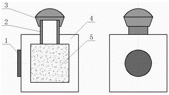
[0044] Such as figure 1 shown.
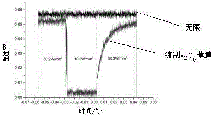
[0045] A wide-band laser protection structure, which includes a sapphire shell 4, and the sapphire shell 4 is deposited with a thickness of 300-400 nm (optimally 350 nm) by magnetron sputtering on the incident surface of the laser light source. The vanadium pentoxide thin film layer 1 is provided with a cavity filled with a carbon nanotube suspension 5 in the sapphire shell 4, and the cavity communicates with the liquid injection port 2 passing through the sapphire shell 4, and the carbon nanotube suspension 5 is injected into the cavity through the liquid injection port 2, and a rubber cap capsule 3 is installed on the end of the liquid injection port 2 outside the sapphire case 4 to isolate the cavity from the outside world. The actual detection device of the protective structure of the present invention is as figure 2 shown.
PUM
| Property | Measurement | Unit |
|---|---|---|
| Surface roughness | aaaaa | aaaaa |
| Thickness | aaaaa | aaaaa |
| Thickness | aaaaa | aaaaa |
Abstract
Description
Claims
Application Information
 - R&D
- Intellectual Property
- Life Sciences
- Materials
- Tech Scout
- Unparalleled Data Quality
- Higher Quality Content
- 60% Fewer Hallucinations
Browse by: Latest US Patents, China's latest patents, Technical Efficacy Thesaurus, Application Domain, Technology Topic, Popular Technical Reports.
© 2025 PatSnap. All rights reserved.Legal|Privacy policy|Modern Slavery Act Transparency Statement|Sitemap|About US| Contact US: help@patsnap.com


