Mode-locked state detecting device and method for femto second fiber laser

A state detection device and technology of femtosecond fiber, applied in the field of laser, can solve the problem of inability to use mode-locking judgment, and achieve the effects of high reliability, high judgment accuracy, and simple structure of the device

Inactive Publication Date: 2017-02-15
NAT TIME SERVICE CENT CHINESE ACAD OF SCI
View PDF5 Cites 3 Cited by
  • Summary
  • Abstract
  • Description
  • Claims
  • Application Information

AI Technical Summary

Problems solved by technology

Therefore, this method cannot be used for mode-locking judgment

Method used


Image

  • Mode-locked state detecting device and method for femto second fiber laser
  • Mode-locked state detecting device and method for femto second fiber laser

Examples


Embodiment 1

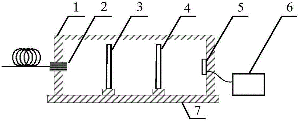
[0023] in figure 1 In the present invention, a femtosecond fiber laser mode locking state detection device includes:

[0024] An optical fiber collimator 2 is installed in the middle of the left inner wall of the box 7 to convert the transmitted light in the optical fiber into collimated light. The optical fiber collimator 2 is installed with a gradient index lens. The pitch of the gradient index lens is It is 0.23, the surface angle is 0°, 15 layers of zirconium dioxide or silicon dioxide antireflection coating is vacuum evaporated on the mirror surface of the gradient index lens, the spectrum of the antireflection coating is 1500~1550nm, the effective focal length is 1.94mm, and the bottom of the box 7 The first band-pass filter 3 is fixedly connected with a screw-fastened connector in the light emission direction, and the second band-pass filter 4 is fixedly connected with a screw-fastened connector in the left light emission direction of the first band-pass filter 3 , The fir...

Embodiment 2

[0026] In the above embodiment 1, 12 layers of zirconium dioxide or silicon dioxide antireflection coating are vacuum-evaporated on the mirror surface of the gradient index lens of this embodiment. The spectrum of the antireflection coating is 1250~1500nm, and the effective focal length is 1.85mm. The center wavelength of the bandpass filter 3 and the second bandpass filter 4 is 1480nm or 1490nm, the bandwidth is 4nm, the center transmittance is 50%, and the photosensitive area of ​​the photodetector 5 is 1mm 2 , The wavelength is 1000-1400nm, the bandwidth is 5MHz, and the remaining parts and the connection relationship of the parts are exactly the same as the first embodiment.

Embodiment 3

[0028] In the above embodiment 1, 18 layers of zirconia or silicon dioxide antireflection coating are vacuum-evaporated on the mirror surface of the gradient index lens of this embodiment. The spectrum of the antireflection coating is 1550-1650nm, and the effective focal length is 1.99mm. The center wavelength of the bandpass filter 3 and the second bandpass filter 4 is 1500nm or 1510nm, the bandwidth is 10nm, the center transmittance is 90%, and the photosensitive area of ​​the photodetector 5 is 10mm 2 , The wavelength is 1600-1700nm, the bandwidth is 5MHz, and the remaining parts and the connection relationship of the parts are exactly the same as in the first embodiment.


PUM


Abstract

The invention relates to a mode-locked state detecting device for a femto second fiber laser. The middle of the left inner wall of a casing is provided with a fiber collimator, a first bandpass filter plate is arranged in the light emergent direction in the bottom of the casing, a second bandpass filter plate is arranged in the left light emergent direction of the first bandpass filter plate, the middle portion of the right inner wall of the casing is provided with a photoelectric detector, the photoelectric detector is electrically connected with a voltage monitoring unit, and the top of the casing is provided with a casing cover. The device can solve the problem that the fiber laser which is characterized by short pulse, high spectral width and high repetition frequency in the precise instrument measuring field cannot determine the mode-locked state when the fiber laser needs to be started automatically, and ensures that the femto second laser can determine the mode-locked state in the operation stage; a corresponding detecting method is simple in operation, and high in determining accuracy, reliability and applicability; and the device and method are suitable for determining the mode-locked state of the femto second laser which is widely applied to the precise measuring field.

Description

Technical field [0001] The invention belongs to the field of laser technology, and specifically relates to a device and method for diagnosing the mode-locking state of a femtosecond fiber laser during its operation. Background technique [0002] The femtosecond optical comb was born at the end of the last century. It can simply and effectively perform optical frequency synthesis and measurement. It has greatly promoted metrology science, especially frequency measurement, and directly led to the development of optical frequency standards. With the development of optical comb technology and the increasing demand from all walks of life, traditional optical comb systems based on Ti:Sapphire mode-locked lasers are expensive, complex in structure, and large in size and power consumption, especially for maintenance and demanding work. The environment and other shortcomings limit its application. In recent years, fiber femtosecond optical comb systems based on fiber femtosecond laser te...

Claims


Application Information

Patent Timeline
Patent Type & Authority Applications(China)
IPC IPC(8): H01S3/098H01S3/067
CPCH01S3/1109H01S3/067
Inventor 陈江张颜艳闫露露张攀姜海峰
Owner NAT TIME SERVICE CENT CHINESE ACAD OF SCI
Why Eureka
Try Eureka