Disc type aircraft

A kind of aircraft and dish-type technology, applied in the field of flight equipment, can solve the problems of high cost, low speed, cumbersome manufacturing process, etc., and achieve the effect of reducing air resistance

Inactive Publication Date: 2017-02-22
吴锜
View PDF12 Cites 2 Cited by
  • Summary
  • Abstract
  • Description
  • Claims
  • Application Information

AI Technical Summary

Problems solved by technology

With the pace of the development of the times, some people boldly proposed a variety of flight plans. In June 2008, the single-propeller ring jointly developed by Harbin Shengshi Special Aircraft Co., Ltd., the Fourth Research Institute of China Aerospace Science and Industry Corporation and the School of Astronautics of Harbin Institute of Technology The "flying saucer" was successfully developed in Harbin. The diameter of the aircraft is about 1.2 meters. It adopts a saucer-shaped ring wing shape design and a special aerodynamic layout. 10 kg, full of fuel can fly in the air for 40 minutes at a time, can be used in aerial photography, geological survey, emergency lighting and temporary communication platform, etc. It has the characteristics of low altitude, low speed, vertical take-off and landing and hovering. With the functions of helicopters and fixed-wing aircraft, it can provide technical support for many fields. The flight is not restricted by region. The flight track can be preset or changed at any time. It can be widely used in aerial photography, geological survey, and high-voltage transmission line inspection. , Oilfield pipeline inspection, highway management, forest fire prevention inspection, poisonous gas exploration, anti-drug, emergency lighting, temporary communication, platform emergency rescue and ambulance, etc.; but its structure is complicated, the manufacturing process is cumbersome, and the cost is high

Method used


Image

  • Disc type aircraft

Examples


Embodiment

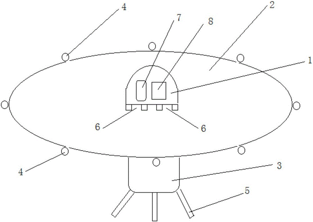
[0017] The main structure of the saucer aircraft involved in this embodiment comprises a high-pressure air chamber 1, a disc body 2, a load compartment 3, an exhaust pipe 4, a floor support 5, an exhaust hole 6, a high-pressure air supply device 7 and an air valve 8; A high-pressure air chamber 1 with an inner hollow streamlined structure is provided at the center of the upper surface of the disc body 2, and 3-12 rectangular-shaped exhaust holes are evenly spaced at the position where the high-pressure air chamber 1 intersects with the disc body 2 6. The inner space of the high-pressure air chamber 1 is provided with a high-pressure air supply device 7 and an air valve 8, the high-pressure air supply device 7 is electrically connected to the air valve 8, and the center of the lower surface of the disc body 2 is provided with an inner hollow rounded rectangular structure. Load bin 3, the bottom of the outer surface of load bin 3 is evenly spaced with 3-6 floor supports 5 of tele...


PUM


Abstract

The invention belongs to the technical field of flight equipment and relates to a disc type aircraft. The aircraft can vertically take off and land. A main body structure comprises a high-pressure air chamber, a disc body, a load bearing bin, exhaust pipes, landing supports, exhaust holes, a high-pressure air flow supply device and an air valve. The high-pressure air flow supply device controls high-pressure air flow to be sprayed along the upper surface of the disc body through the exhaust holes, so the disc body generates raising force larger than the gravity of the disc type aircraft, and the disc type aircraft starts to ascend and take off; The exhaust pipes at corresponding positions are controlled to be opened and closed through the air valve so that the disc type aircraft can fly in different directions, and the disc type aircraft can move forward and backward, hover, horizontally move and steer; the aircraft can be manufactured into a remote control toy, an air photography device, a low-altitude ground reconnaissance device, an agricultural condition inspection device, a disaster scene rescue device and an offshore area detection and rescue device. The aircraft is simple in structure, scientific and reasonable in principle, safe and reliable in performance, low in manufacturing and maintenance cost, and convenient to operate and maintain, and the flight environment is friendly.

Description

[0001] Technical field: [0002] The invention belongs to the technical field of flying equipment, and relates to a saucer-type aircraft capable of vertical take-off and landing, translational flight, turning or hovering in the air, used as a remote control toy, aerial photography, low-altitude ground reconnaissance, agricultural situation investigation, and disaster relief. It is used for on-site ball search and offshore field detection and search and rescue. [0003] Background technique: [0004] Aircraft refers to man-made flying objects that can fly off the ground and fly in space, and are artificially controlled to fly in the atmosphere or outside the atmosphere (space), and are used in scientific exploration, ocean and military fields; aircraft are generally divided into There are five categories of aircraft, spacecraft, rockets, missiles and guided weapons: aircraft flying in the atmosphere are called aircraft, including balloons, gliders, airships, airplanes and helico...

Claims


Application Information

Patent Timeline
IPC IPC(8): B64C39/06B64C29/00
CPCB64C39/001B64C29/0016
Inventor 吴锜吴开震吴若谷吴若鼎吴若尧
Owner 吴锜
Why Eureka
Try Eureka