
Calcining device

A calcination device and calcination furnace technology, which is applied in the direction of charging processing type, lighting and heating equipment, furnace components, etc., can solve the problems of uneven calcination on the surface, easy backflow of condensed water, inconvenient picking and placing of powder raw materials, etc.

Active Publication Date: 2017-02-22
DEMETER SUZHOU ELECTRONICS ENVIRONMENTAL MATERIALS CO LTD
View PDF3 Cites 1 Cited by
  • Summary
  • Abstract
  • Description
  • Claims
  • Application Information

AI Technical Summary

Problems solved by technology

[0004] Based on this, it is necessary to provide a calcination device for the technical problems of inconvenient access to powder raw materials, uneven surface calcination, and easy reflux of condensed water.

Method used


Image

  • Calcining device
  • Calcining device
  • Calcining device

Examples


Embodiment Construction

[0017] In order to make the above objects, features and advantages of the present invention more clearly understood, the specific embodiments of the present invention will be described in detail below with reference to the accompanying drawings. In the following description, numerous specific details are set forth in order to provide a thorough understanding of the present invention. However, the present invention can be implemented in many other ways different from those described here, and those skilled in the art can make similar improvements without departing from the connotation of the present invention, so the present invention is not limited by the specific embodiments disclosed below.

[0018] In describing the present invention, it should be understood that the terms "center", "longitudinal", "transverse", "length", "width", "thickness", "upper", "lower", "front", " Back", "Left", "Right", "Vertical", "Horizontal", "Top", "Bottom", "Inner", "Outer", "Clockwise", "Coun...


PUM


Abstract

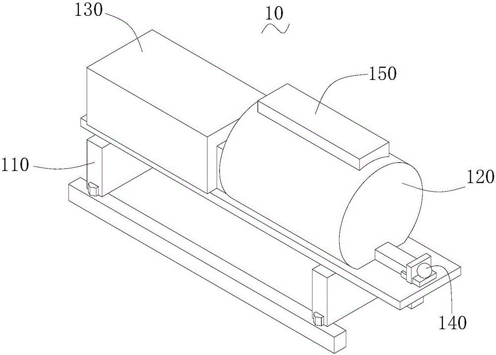
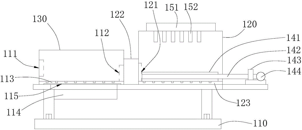
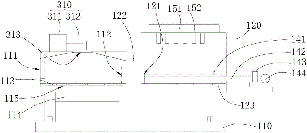
The invention relates to a calcining device. The calcining device comprises a rack, a calcining furnace, a drying furnace, a drainage assembly, a heating assembly and a spraying device; a first sliding rail is arranged on the side wall inside the calcining furnace; a second sliding rail connected with the first sliding rail is arranged on the side wall inside the drying furnace; a drier is arranged at the bottom of the calcining furnace; the drainage assembly comprises a guide pipe and an exhaust fan; the heating assembly comprises a graphite plate, a heat conduction pipe, a heat conduction oil pump and a heat conduction oil heater; the spraying device is arranged outside the calcining furnace; the spraying device comprises an atomizer and a plurality of atomizing spray heads connected with the atomizer respectively; and the atomizing spray heads arranged at the top of the calcining furnace in a penetrating manner face the first sliding rail. According to the calcining device, powder raw materials after pretreatment are uniformly calcined on the surface during deep calcining, so that the calcining effect is outstanding, the product yield is high, and the product quality of the calcined powder raw materials is improved; and moreover, moist air at the upper end is prevented from being condensed after precooling to form condensate water, so that the drying treatment efficiency is improved.

Description

technical field [0001] The invention relates to the technical field of powder raw material processing, in particular to a calcining device. Background technique [0002] The traditional calcination device often encounters uneven heating during calcination of powder raw materials, and it is inconvenient to take and place during use, which will greatly affect the quality of the product and bring great trouble to the operator. . At the same time, the traditional calcination device does not pre-dry the powder raw material, which leads to uneven calcination of the powder raw material and affects the yield of the powder raw material calcination. [0003] In addition, the steam exhaust pipe during the drying process is directly arranged vertically, and the upper end is pre-cooled to condense to form condensed water. The condensed water is easy to flow back, which affects the processing efficiency. Contents of the invention [0004] Based on this, it is necessary to provide a ca...

Claims


Application Information

Patent Timeline
IPC IPC(8): F27B19/04F26B17/00F26B25/00F27B9/24F27B9/36F27B9/30F27D7/02
CPCF26B17/00F26B25/00F27B9/24F27B9/30F27B9/36F27B19/04F27B2009/3607F27D7/02F27M2003/03
Inventor 周利虎刘宇杰宋军
Owner DEMETER SUZHOU ELECTRONICS ENVIRONMENTAL MATERIALS CO LTD
Learn More