A terahertz-driven subfemtosecond time-resolved streak camera

A time-resolved, streak camera technology, used in devices and instruments for measuring time intervals, can solve problems such as the need for a power-driven system and limit time resolution, and achieve the effects of good synchronization, improved order of magnitude, and simple structure

Active Publication Date: 2018-12-14
XI'AN INST OF OPTICS & FINE MECHANICS - CHINESE ACAD OF SCI
View PDF7 Cites 0 Cited by
  • Summary
  • Abstract
  • Description
  • Claims
  • Application Information

AI Technical Summary

Problems solved by technology

The device uses a radio frequency cavity (rf cavity) to deflect high-energy electrons, but the phase jitter between the radio frequency field and the electron pulse limits the time resolution in the accumulation mode, generally greater than 100fs
At the same time, RF deflection of high-energy electron beams utilizes high-power RF fields, requiring expensive and complex power drive systems

Method used


Image

  • A terahertz-driven subfemtosecond time-resolved streak camera
  • A terahertz-driven subfemtosecond time-resolved streak camera
  • A terahertz-driven subfemtosecond time-resolved streak camera

Examples


Embodiment 1

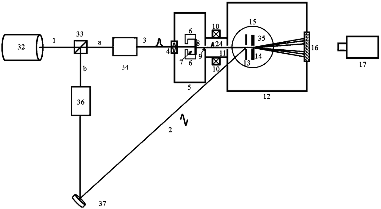
[0034] Such as figure 1 and figure 2 As shown, the streak camera includes a femtosecond laser 32, a beam splitter 33, an ultraviolet pulse generator 34, a DC electron gun, a DC gun magnetic focusing device 10, a deflection yoke 35, a fluorescent screen 16, and an EBCCD camera 17;

[0035] The femtosecond laser (a) emitted by the femtosecond laser 32 passes through the beam splitter 33 and then a beam of femtosecond laser enters the ultraviolet laser pulse generator 34, and another beam of femtosecond laser (b) enters the deflection yoke 35;

[0036] The DC electron gun comprises a DC electron gun chamber 5, a first lens 4, a cathode assembly and an anode 9; the front end of the DC electron gun chamber 5 is equipped with the first lens 4, and the rear end is provided with an anode 9; the cathode assembly is installed in the DC electron gun chamber 5; The assembly and anode 9 generate an accelerating electric field; the cathode assembly includes a cathode frame 6, a metal cath...

Embodiment 2

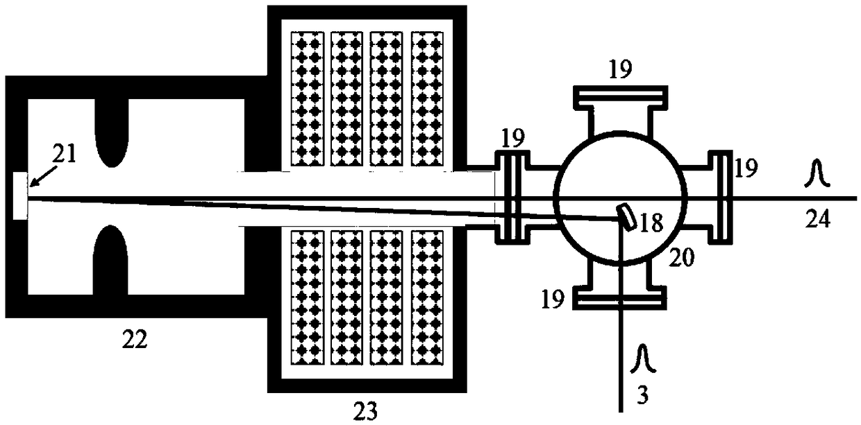
[0044] The invention can not only be used to characterize non-relativistic electrons accelerated by a DC gun, but also can characterize the time characteristics of relativistic ultrafast electron pulses. The specific embodiment is to use an RF accelerating gun to accelerate electron beams. image 3 Shown is a schematic diagram of the structure of the RF accelerator gun,

[0045] A bundle of femtosecond laser pulses (a) generates ultraviolet light pulses through the ultraviolet light pulse generator, and the ultraviolet light pulses pass the ultraviolet laser pulses through the second vacuum flange 19 (the second vacuum flanges are evenly distributed outside the laser chamber, a total of four 1) is introduced into the laser chamber; the ultraviolet light pulse 3 is reflected and irradiated on the photocathode 21 in the radio frequency chamber 22 through the reflection mirror 18 in the laser chamber 20, and the external photoelectric effect occurs, which is generated in the ultra...


PUM


Abstract

The invention belongs to the field of ultrafast diagnosis, and particularly relates to a terahertz-driven sub-femtosecond time-resolved streak camera. The camera comprises a femtosecond laser device, a beam splitter, an ultraviolet laser pulse generation device, an electronic gun, a magnetic focusing device, a deflection system, a fluorescent screen and an EBCCD camera; after femtosecond laser emitted by the femtosecond laser device passes through the beam splitter, one femtosecond laser beam enters the ultraviolet laser pulse generation device, and the other femtosecond laser beam enters the deflection system; the electronic gun is used for converting ultraviolet laser pulses generated by the ultraviolet laser pulse generation device into electronic pulses and accelerating the electronic pulses; the magnetic focusing device is installed between the electronic gun and the deflection system; the EBCCD camera is installed at the position, directly facing the fluorescent screen, outside a main vacuum chamber. According to the streak camera, the time characteristics of the non-relativistic and relativistic ultrafast electronic pulses can be detected, and the resolution can reach the magnitude of a few femtoseconds.

Description

technical field [0001] The patent of the invention belongs to the field of ultrafast diagnosis, and specifically relates to a terahertz-driven sub-femtosecond time-resolved streak camera. Background technique [0002] The generation of ultrafast electrons, the manipulation of their trajectory, and the characterization of their time characteristics are key technologies in the field of ultrafast research, and are generally closely related to ultrafast laser technology. [0003] At present, ultrafast optical pulses can reach the order of sub-100 fs or even as, and the corresponding ultrafast electronic pulses can also be compressed to the order of hundreds of fs or even several fs. However, the measurement of electronic pulses with this time precision is still facing challenges. Especially in experiments such as seed source of X-ray free electron laser, ultrafast electron diffraction and electron rescattering in atoms, a comprehensive understanding of the temporal characterist...

Claims


Application Information

Patent Timeline
Patent Type & Authority Patents(China)
IPC IPC(8): G04F13/02G04F13/00
CPCG04F13/00G04F13/026
Inventor 惠丹丹田进寿罗端温文龙王兴
Owner XI'AN INST OF OPTICS & FINE MECHANICS - CHINESE ACAD OF SCI
Why Eureka
Try Eureka