

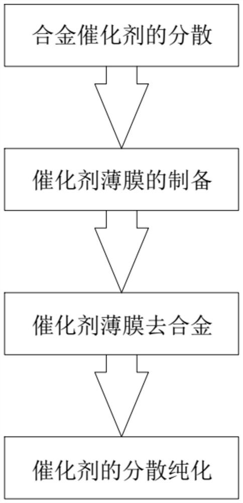
A method for catalyst dealloying
A dealloying and catalyst technology, applied to electrochemical generators, fuel cells, structural parts, etc., can solve the problems of waste, inability to take out, and processing capacity of only mg level, so as to improve activity and stability, and improve utilization The effect of efficiency and convenient recycling
- Summary
- Abstract
- Description
- Claims
- Application Information
AI Technical Summary
Problems solved by technology
Method used
Image

Examples
preparation example Construction
[0024] S2, the preparation of catalyst film, the catalyst solution in step S1 is obtained catalyst film on a conductive inert electrode by filtering or coating; when filtering, the filtration efficiency is accelerated by means of pressurization; the mode of coating can be Use ultrasonic spraying technology or direct manual coating; the inert electrode can be one of carbon paper, carbon cloth, and porous titanium mesh.
[0025] S3, the catalyst film is dealloyed, and the catalyst film in step S2 is dealloyed by electrochemical means to obtain a dealloyed catalyst film, and the time for the electrochemical process is between 1 min and 1 h, preferably between 5 min and 30 min. ; The electrochemical method is to apply voltage or current in acidic solution for alloying treatment. The applied voltage can be cycle voltage, square wave, constant voltage, pulse voltage, and the applied current can be cycle current, constant current, pulse current. Voltage and current can be used accord...
Embodiment 1
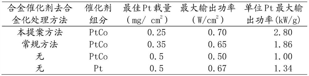
[0027] Embodiment 1: Electrochemical dealloying treatment to PtCo alloy catalyst
[0028] The first step is to prepare a catalyst thin film. Take 0.6g of PtCo catalyst powder and add 100mL of water and ethanol mixture into a small glass bottle (v water / v alcohol = 1 / 4), disperse in a high-speed shear emulsifier for 15min (speed 8000rpm), and then filter Put an effective area of 50cm 2 carbon paper, under a pressure of 0.05Mpa, the alloy catalyst feed liquid is filtered to form a filter membrane (catalyst film), and when there is basically no solution on the surface of the membrane, the filter is stopped, and then 200mL deionized water is added to repeat the filter operation, and so repeated three times, the loaded The carbon paper of the catalyst thin film is taken out.
[0029] In the second step, electrochemical dealloying is performed on the catalyst. Put the carbon paper loaded with the catalyst film into the electrochemical cell, slowly add 0.5M H along the container...
Embodiment 2
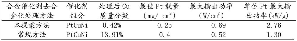
[0036] Embodiment 2: to the electrochemical dealloying treatment of PtCuNi alloy catalyst
[0037] The first step is to prepare a catalyst thin film. Take 0.6g of PtCuNi catalyst powder, add water and ethanol mixture 100mL (v water / v alcohol = 1 / 4) in a small glass bottle, disperse under the high-speed shear emulsifier for 15min (rotating speed 8000rpm), and then on a filter device Put an effective area of 50cm 2 carbon paper, under a pressure of 0.05Mpa, the catalyst feed liquid is filtered to form a filter membrane (catalyst film), and the filter is stopped when there is substantially no solution on the surface of the membrane. Then add 200mL of deionized water to repeat the filtration operation, repeat this three times, and take out the carbon paper loaded with the catalyst film.
[0038] In the second step, electrochemical dealloying is performed on the catalyst. Put the carbon paper loaded with the catalyst film into the electrochemical cell, slowly add 0.5M H along ...
PUM
 Abstract
Description
Claims
Application Information