
Wireless power supply system for in-wheel motors based on magnetic coupling resonance

A technology of magnetic coupling resonance and in-wheel motors, applied in the direction of circuit devices, electrical components, etc., can solve problems such as cable short circuit, loose connection, fire, etc., achieve voltage stability, ensure constant voltage power supply, and simplify system control.

Active Publication Date: 2018-12-11
HARBIN INST OF TECH
View PDF7 Cites 0 Cited by
  • Summary
  • Abstract
  • Description
  • Claims
  • Application Information

AI Technical Summary

Problems solved by technology

[0003] The present invention is to solve the problem that the traditional in-wheel motors are powered by cables, and it is easy to loosen, fall off or even leak electricity at the wiring, which will adversely affect the operation of the vehicle. At the same time, the aging of the cables will cause a short circuit, which may cause a fire in severe cases

Method used


Image

  • Wireless power supply system for in-wheel motors based on magnetic coupling resonance
  • Wireless power supply system for in-wheel motors based on magnetic coupling resonance
  • Wireless power supply system for in-wheel motors based on magnetic coupling resonance

Examples


specific Embodiment approach 1

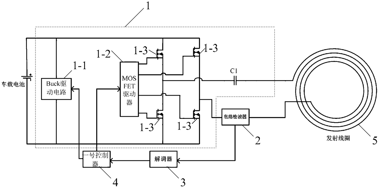
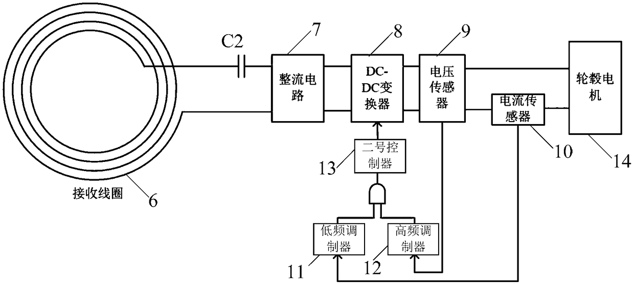
[0021] Specific implementation mode one: refer to figure 1 and figure 2 Describe this embodiment in detail, the in-wheel motor wireless power supply system based on magnetic coupling resonance described in this embodiment includes an energy transmitting device and an energy receiving device,

[0022] The energy transmitting device comprises an energy excitation circuit 1, an envelope detector 2, a demodulator 3, a No. 1 controller 4 and a transmitting coil 5,

[0023] The energy receiving device includes a receiving coil 6, a capacitor C2, a rectifier circuit 7, a DC-DC converter 8, a voltage sensor 9, a current sensor 10, a low frequency modulator 11, a high frequency modulator 12 and a second controller 13,

[0024] The energy excitation circuit 1 includes a Buck drive circuit 1-1, a MOSFET driver 1-2 and four metal-oxide-semiconductor field-effect transistors 1-3 to form an inverter circuit,

[0025] The on-vehicle battery supplies power to the energy excitation circuit ...

specific Embodiment approach 2

[0034] Specific embodiment 2: This embodiment is a further description of the in-wheel motor wireless power supply system based on magnetic coupling resonance described in specific embodiment 1. In this embodiment, it also includes a capacitor C1, which is connected in series with the transmitting coil 5. The capacitor C1 and the transmitting coil form an LC resonant circuit, the capacitor C2 and the receiving coil 6 form an LC resonant circuit, and the resonant frequency is f.

[0035] In this embodiment, the transmitting coil 5 and the receiving coil 6 can generate resonant coupling, and when the frequency of the current in the two coils is the same, the motor can obtain a constant output voltage.

specific Embodiment approach 3

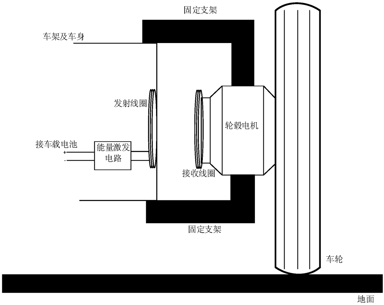
[0036] Specific implementation mode three: refer to image 3 Describe this embodiment in detail. This embodiment is a further description of the in-wheel motor wireless power supply system based on magnetic coupling resonance described in Embodiment 1. In this embodiment, the receiving coil 6 is circular, hexagonal, rectangular or The oval shape is integrated with the hub motor; the transmitter coil 5 is circular, hexagonal, rectangular or elliptical, and is integrated with the vehicle frame.


PUM


Abstract

The invention provides a wheel hub motor wireless power supply system based on magnetic coupling resonance, relates to the technical field of wireless electric energy transmission, and aims at solving the problems that a conventional wheel hub motor uses a cable for supplying electricity, and a wire connection position can easily become loose, can easily fall or even generate electricity leakage, so that the adverse influence is brought to vehicle operation; meanwhile, short circuit can be caused by cable aging; in severe cases, fire hazards can be caused. A vehicle-mounted battery supplies electricity to an energy stimulation circuit; the energy simulation circuit converts direct current electricity into alternating current electricity to be sent to an emitting coil; the alternating current electricity generates induced electromotive force with a receiving coil so as to supply the electricity to the wheel hub motor; a voltage value and a current value of the wheel hub motor are collected, and are used as driving signals of a DC-DC converter after being subjected to modulation and the operation, and are used for regulating the impedance of a wheel hub. An envelope detector detects current signals in the emitting coil and performs demodulation and processing to generate PWM (pulse-width modulation) signals to regulate a driving signal duty ratio of a Buck driving circuit; the stable load voltage is realized; wireless charging is performed on the direct current wheel hub motor.

Description

technical field [0001] The invention relates to a wireless power supply system for hub motors based on magnetic coupling resonance. It belongs to the technical field of wireless power transmission. Background technique [0002] Electric vehicles are gaining more and more attention due to their environmental advantages. Hub motor is one of the core components of electric vehicles, which determines the operating performance of electric vehicles. Traditional in-wheel motors are powered by cables. In the high-speed, high-temperature, high-pressure, and high-friction internal environment of the wheel, it is easy for the wiring to become loose, fall off, or even leak electricity, which will adversely affect the operation of the vehicle. At the same time, the aging of the cable will cause a short circuit, which may cause a fire in severe cases. Therefore, there is a potential safety hazard in the traditional way of powering the hub motor. Contents of the invention [0003] Th...

Claims


Application Information

Patent Timeline
Patent Type & Authority Patents(China)
IPC IPC(8): H02J50/12
Inventor 朱春波杨光宋凯
Owner HARBIN INST OF TECH
Learn More