Supercharge Your Innovation With Domain-Expert AI Agents!

Transformer circuit and method for ion current measurement of spark plugs

A transformer circuit and ion current technology, which is applied in the direction of circuits dedicated to spark gaps, spark plugs, spark ignition controllers, etc., can solve the problems of complex feasibility and impossibility to be popularized

Active Publication Date: 2019-06-25
BORGWARNER BERU SYST
View PDF10 Cites 0 Cited by
  • Summary
  • Abstract
  • Description
  • Claims
  • Application Information

AI Technical Summary

Problems solved by technology

However, its feasibility is very complex, so it is unlikely to be popularized

Method used


Image

  • Transformer circuit and method for ion current measurement of spark plugs
  • Transformer circuit and method for ion current measurement of spark plugs
  • Transformer circuit and method for ion current measurement of spark plugs

Examples


Embodiment Construction

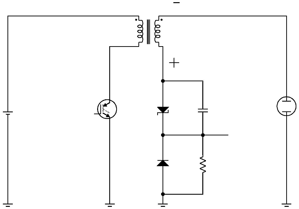
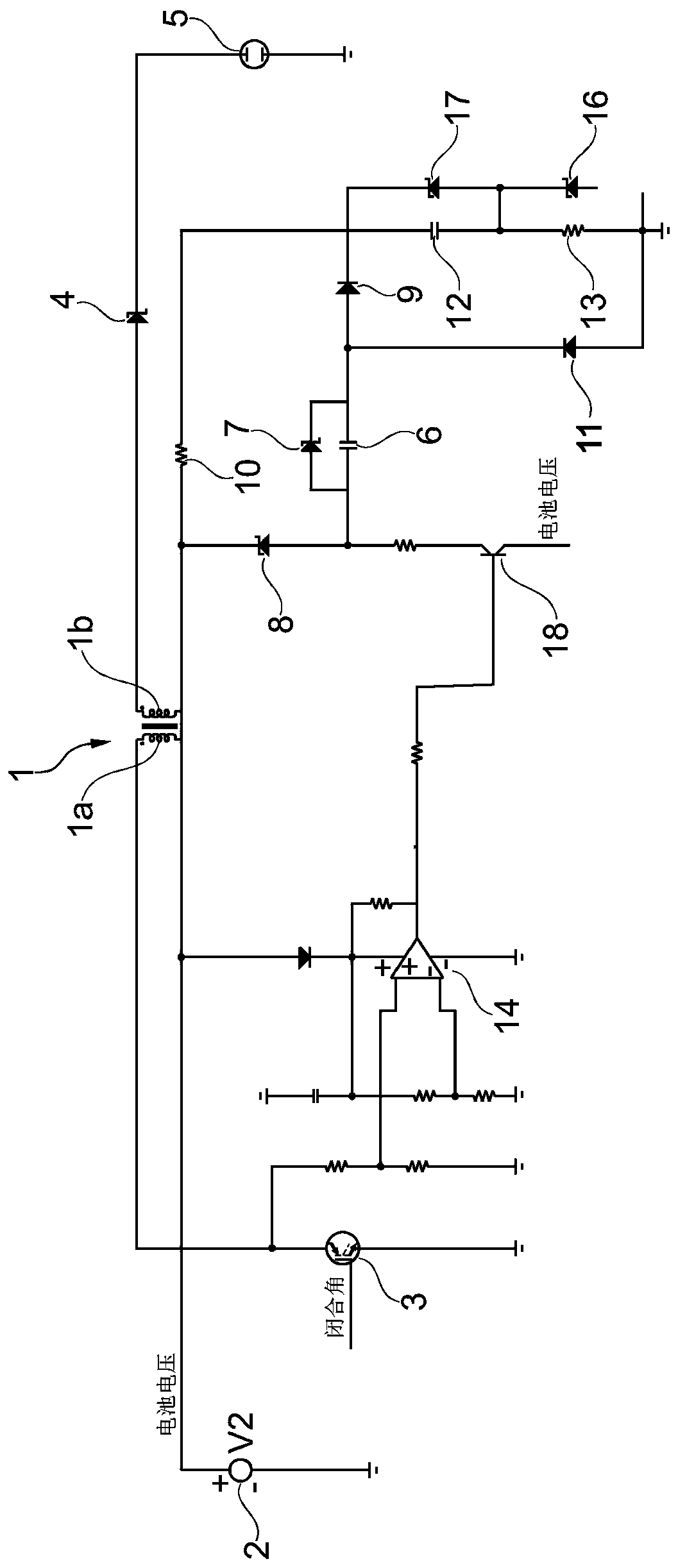
[0019] figure 2 The transformer circuit in has a primary circuit coupled through a transformer 1 and a secondary circuit. The primary circuit comprises a connector for a primary voltage source 2 (eg a vehicle battery), a primary side 1 a of a transformer 1 and a switch 3 (eg a transistor switch). When the switch 3 is closed, the primary current flows through the primary side 1 a of the transformer 1 , with the result that a secondary voltage is induced in the secondary side 1 b of the transformer 1 . The primary side 1 a and the secondary side 1 b can be designed as coils coupled via the core of the transformer 1 .

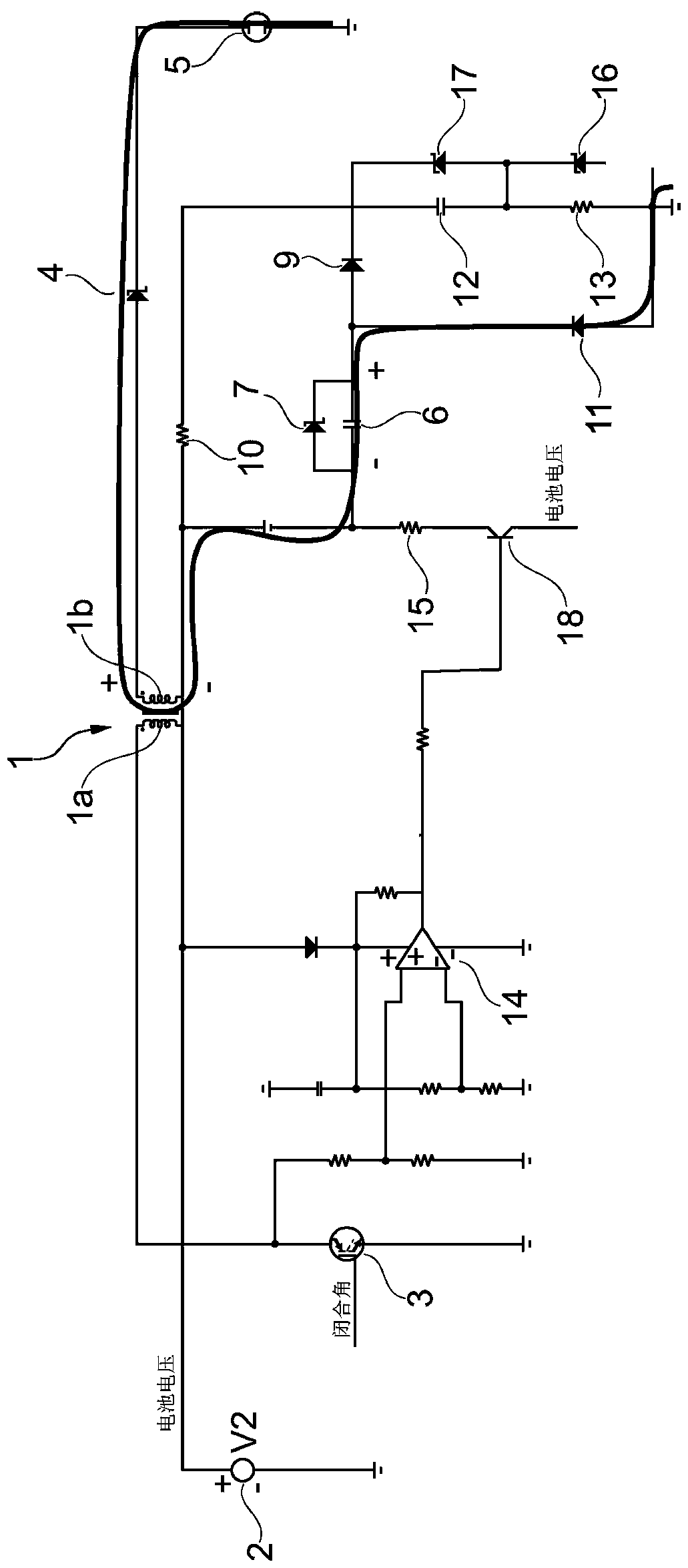
[0020] In the secondary circuit, the secondary side 1b of the transformer 1 is connected in series to a conduction spark suppression diode 4 and a connector for the spark plug 5 so that the secondary voltage generates an arc between the electrodes of the spark plug 5 . image 3 The basic path of the secondary current flowing when the arc discharge is ignited is...


PUM


Abstract

A voltage transformer circuit is described for supplying a spark plug with ignition energy and for ionic current measurement. A transformer of the circuit generates a secondary voltage from a primary voltage and applies the secondary voltage to the spark plug to ignite an electric arc. Using a current effected by the secondary voltage, a capacitor is charged to a breakdown voltage of a Zener diode bridging the same, via a first branch, which leads from the transformer to a first of two sides of the capacitor. The primary voltage is disconnected from the transformer in order to extinguish the electric arc. The capacitor delivers charges for an ionic current via a second branch, which connects the second side of the capacitor to the transformer. A measuring signal of the ionic current is obtained by measuring a voltage drop at a measuring resistor.

Description

technical field [0001] The invention relates to a spark plug transformer circuit and an ion current measuring method. Background technique [0002] To ignite fuel in the engine's combustion chamber, an arc discharge is created by applying high voltage between the electrodes of the spark plug. By applying a slightly lower voltage, the conductivity of the gas mixture between the electrodes of the spark plug can be measured if no arcing has ignited. Such ion current measurements make it possible to obtain valuable information about the engine's combustion chambers. US patent US5866808 and German publication DE3934310A1 disclose ignition systems that can be used for ion current measurements. [0003] This type of ignition system consists of a spark plug and a transformer circuit that generates a secondary voltage of more than 10kV through the transformer from the primary voltage, which is generally the vehicle's on-board system voltage. When the primary voltage is applied to ...

Claims


Application Information

Patent Timeline
Patent Type & Authority Patents(China)
IPC IPC(8): F02P17/00F02P3/04
CPCH01T15/00F02P3/0435F02P3/08F02P17/12F02P2017/125H01T13/40H01T13/50
Inventor D·维斯滕哈根
Owner BORGWARNER BERU SYST
Features
  • R&D
  • Intellectual Property
  • Life Sciences
  • Materials
  • Tech Scout
  • Unparalleled Data Quality
  • Higher Quality Content
  • 60% Fewer Hallucinations
Learn More