
Alumina carrier hydrogenation catalyst regeneration utilization method

A hydrogenation catalyst, alumina carrier technology, applied in metal/metal oxide/metal hydroxide catalysts, physical/chemical process catalysts, chemical instruments and methods, etc. Over temperature and other problems, to achieve the effect of good activity and stability, recovery of pore volume, recovery of activity and stability

Active Publication Date: 2017-03-08
JIANGSU KECHUANG PETROCHEM
View PDF4 Cites 2 Cited by
  • Summary
  • Abstract
  • Description
  • Claims
  • Application Information

AI Technical Summary

Problems solved by technology

In the past, most hydrogenation catalysts in my country used this regeneration method, but there are four fatal shortcomings in this regeneration: (1) The regeneration gas will cause corrosion to the equipment of the reaction system
To alleviate this corrosion, either increase the material requirements, or pre-sulfurize the regenerated catalyst, build a vulcanization facility that will only be used for 1-3 years, and increase the investment in the device
(2) Loss of catalyst activity
In the reactor, especially when regenerating in a large-scale reactor, the temperature distribution of the catalyst bed is uneven, and it is easy to locally overheat, resulting in the loss of catalyst activity
(3) pollute the environment
A large amount of gas is generated during regeneration in the device. These gases are extremely difficult to collect and process, and are often discharged into the atmosphere, causing environmental pollution.
(4) Unplanned downtime loss
When regenerating in the reactor, it often takes up the start-up production time, thus affecting the normal economic benefits of the plant

Method used


Image

  • Alumina carrier hydrogenation catalyst regeneration utilization method
  • Alumina carrier hydrogenation catalyst regeneration utilization method
  • Alumina carrier hydrogenation catalyst regeneration utilization method

Examples


Embodiment Construction

[0021] The technical solutions of the present invention will be further described below through specific examples.

[0022] A method for regenerating and utilizing an alumina carrier hydrogenation catalyst, comprising the following steps:

[0023] (1) Sieve the spent catalyst through an 18-mesh vibrating sieve, remove useless carbon powder and ceramic balls, and separate the catalyst to be born;

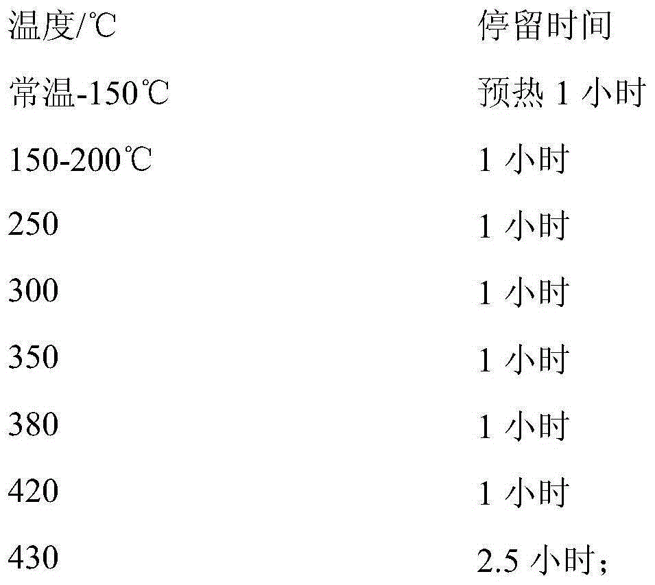
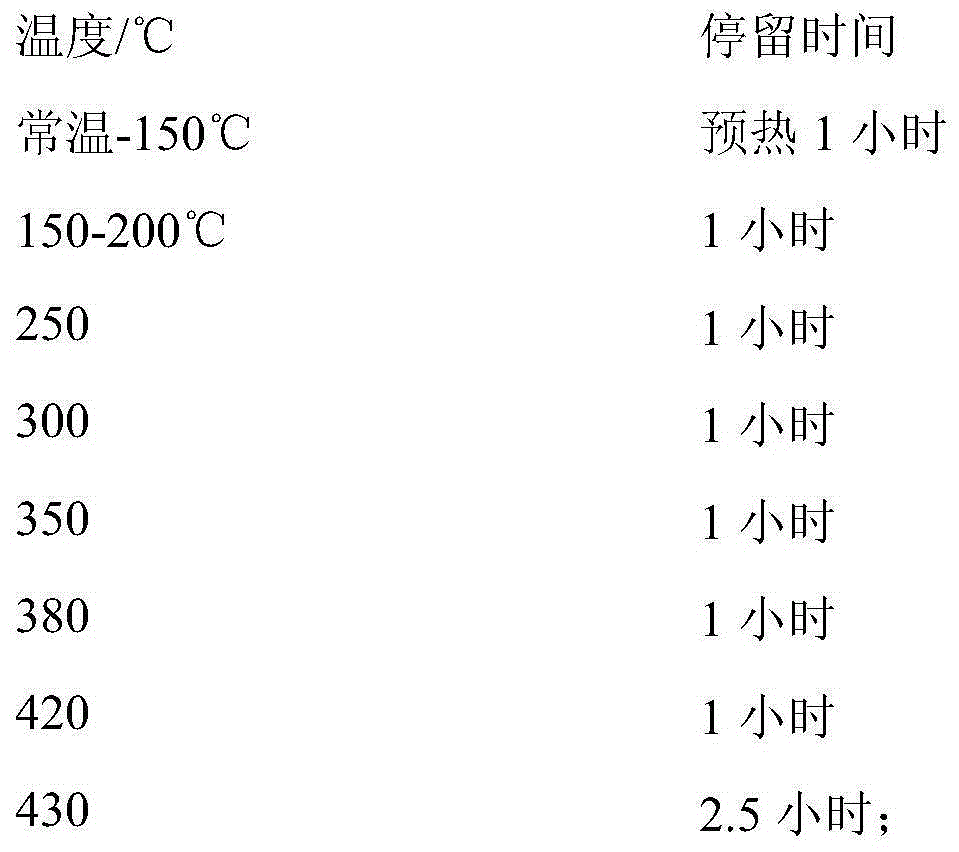
[0024] (2) Send the raw catalyst into the "mesh belt moving bed" type flame-chamber tunnel regeneration furnace with natural gas as fuel, the thickness of the material layer is 35-40 mm, and the speed of the mesh belt is 4 m / hour, and it is carried out continuously through different temperature sections. Heating, and finally cooling down the material to obtain the primary product of the regenerated catalyst;

[0025] The process conditions are:

[0026]

[0027] (3) Sieve the primary product of the regenerated catalyst through an 18-mesh vibrating sieve to obtain a qualified reg...


PUM


Abstract

The present invention discloses an alumina carrier hydrogenation catalyst regeneration utilization method, which comprises: screening a failure catalyst through a vibration sieve to remove unwanted carbon powder and ceramic balls so as to separate a spent catalyst; conveying the spent catalyst into a mesh belt moving bed type flame separation tunnel regeneration furnace using natural gas as a fuel, continuously heating through different temperature sections, cooling, and discharging the material to obtain a regeneration catalyst primary product, wherein the thickness of the material layer is 35-40 mm, and the mesh belt speed is 4 m / h; and screening the regeneration catalyst primary product through the vibration sieve to remove the carbon powder and the ceramic balls to obtain the qualified regeneration catalyst. According to the present invention, by controlling the moving speed of the material layer in the furnace, the charring quality can be ensured, the strength, the specific surface area and the pore capacity of the failure catalyst can be recovered, the activity and the stability of the catalyst can be well recovered, the regeneration catalyst activity recovery rate can achieve more than 90% of the activity of the new catalyst, and the practical value is provided.

Description

technical field [0001] The invention belongs to the technical field of application of hydrogenation catalysts, and relates to a method for regeneration and utilization of alumina carrier hydrogenation catalysts. Background technique [0002] The petroleum and chemical industry is one of the most basic and largest three pillar industries in contemporary society, and it is closely related to the energy and material industries. The development of the petrochemical industry is inseparable from catalysts. If catalysts are not used for many important petrochemical processes, the chemical reaction speed is very slow, or industrial production cannot be carried out at all. It is estimated that more than 80% of the production in the modern fuel industry and chemical industry uses catalytic processes. From 1985 to 1995, the annual consumption of catalysts increased from 84,000 tons to 306,000 tons, showing a rapid upward trend, and among the newly developed products, the proportion of...

Claims


Application Information

Patent Timeline
IPC IPC(8): B01J23/94B01J23/888B01J23/882B01J23/883
Inventor 顾齐欣孙建宜
Owner JIANGSU KECHUANG PETROCHEM
Learn More