Fancy spiral electronic waste pyrolysis device

A technology of pyrolysis of e-waste, which is applied in special forms of dry distillation, indirect heating of dry distillation, petroleum industry, etc., can solve the problems affecting the straight screw conveying materials, the pyrolysis process of e-waste cannot be continuous, and improve the conveying capacity, so as to achieve partitioning Precise control of temperature, improvement of internal spiral tar bonding, and avoiding the effects of adhesion and hardening

Pending Publication Date: 2017-03-08
SHENWU TECH GRP CO LTD
View PDF1 Cites 2 Cited by
  • Summary
  • Abstract
  • Description
  • Claims
  • Application Information

AI Technical Summary

Problems solved by technology

In the temperature range where tar is produced, because there are solids and melts in the material when the tar is just produced, the tar has the opportunity to stick the solid slag together. Rotating together with the screw shaft, through the accumulation of materials, it will eventually affect the ability of the straight screw to convey materials, and even block or block the heating screw, making the electronic waste pyrolysis process unable to continue or the experimental device damaged, which brings great difficulties to the production machine experiment. For example, the patent No. CN104593090A discloses a method and device for preparing synthesis gas by pyrolysis and gasification of biomass, and proposes a method and device for preparing synthesis gas by pyrolysis and gasification of biomass, wherein the method includes low temperature The three stages of roasting, high-temperature catalytic gasification and microwave reforming are carried out continuously in three relatively independent spaces in the gasification device, so as to obtain high-quality syngas
The device includes a biaxial spiral pyrolysis reactor, the front section is a roasting section, the middle section is a gasification section, and the last section is a microwave-assisted reforming section. The combination of internal and external heat of heat, catalyst heat and microwave-assisted heating provides the appropriate temperature for the three reaction stages to realize graded pyrolysis and gasification. The deactivated catalyst and coke are fed into the combustion furnace to generate high-temperature flue gas and catalyst regeneration. However, the device adopts a double-helix design and the double-helix synchronous rotation can only simply increase the conveying capacity, and cannot solve the problem of tar sticking

Method used


Image

  • Fancy spiral electronic waste pyrolysis device
  • Fancy spiral electronic waste pyrolysis device
  • Fancy spiral electronic waste pyrolysis device

Examples


Embodiment 1

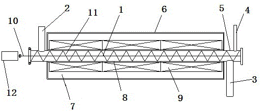
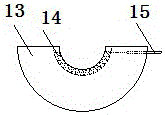
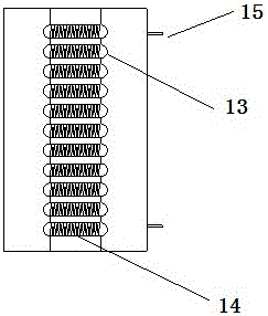
[0032] Embodiment 1: The electric heating system is heated by an electric heating wire, the diameter of the electric heating wire is 1.4mm, and the total length is 15m. Electronic waste materials (mainly circuit boards, wires and keyboards) are made into 3-6mm particles, and the amount of imported materials is 1kg / h, the final pyrolysis slag is 0.8kg / h, and the pyrolysis oil gas is 0.286 Nm3 / h, which realizes continuous material in and out. During the pyrolysis process, the temperature is kept at 600°C, and the heat source is very stable. By using the fancy screw to propel the material, the problem of tar sticking is reduced, and the oil sticking on the pipe wall can be scraped off, which solves the problem that the screw is easy to block. The pitch of the fancy screw is 54mm, and the thickness of the screw blade is 8mm, the helix rotates in the counterclockwise direction, and each turn of the helix is ​​counterclockwise to set a 15° opening gap every 60°, the slag and gas are...

Embodiment 2

[0036] Example 2: The diameter of the heating wire is 1.4mm, and the total length is 15m. Electronic waste materials (circuit boards, wires, keyboards, etc.) are made into 3-6mm particles, and the amount of imported materials is 1kg / h. The slag material is 0.7kg / h, and the pyrolysis oil gas produced is 0.225 Nm3 / h, which realizes continuous material in and out. During the pyrolysis process, the temperature is kept at 600°C, and the heat source is very stable. By using the fancy screw to propel the material, the problem of tar sticking is reduced. The pitch of the fancy screw is 54mm, the thickness of the screw blade is 8mm, the screw rotates counterclockwise, and each turn of the screw is set at 15 degrees counterclockwise every 45° ° opening gap, slag discharge and gas discharge are continuous and smooth, and can ensure that the pressure inside the spiral casing is stable, and the pressure fluctuation range is 3~5kpa.

[0037] The oil and gas assay components are as follows:...


PUM

PropertyMeasurementUnit
thicknessaaaaaaaaaa
distanceaaaaaaaaaa
thicknessaaaaaaaaaa

Abstract

The invention relates to the technical field of waste treatment, in particular to a fancy spiral electronic waste pyrolysis device. The device comprises an electronic waste pyrolysis reactor and an electric heating system, wherein the electronic waste pyrolysis reactor comprises a material pyrolysis assembly and a reactor shell. The material pyrolysis assembly comprises a spiral sleeve and a fancy spiral. The fancy spiral is located inside a temperature section where tar is generated inside the spiral sleeve, and the fancy spiral comprises a spiral shaft and fancy spiral blades, and each fancy spiral blade is provided with a plurality of opening gaps with angles; the electric heating system comprises a heating module and an insulation layer, the insulation layer is located on the outer side of the spiral sleeve inside the closed space, and the heating module is arranged on the outer surface of the insulation layer. The device adopts the fancy spiral blades for conveying raw materials, the materials are stressed in the axial and tangential directions when passing through the fancy spiral blades, adhesion and hardening of the materials are avoided, and blockage is avoided.

Description

technical field [0001] The invention relates to the technical field of waste treatment, in particular to a fancy spiral electronic waste pyrolysis device. Background technique [0002] Due to the continuous change of temperature in the pyrolysis process of electronic waste, the products produced by pyrolysis of materials at different temperatures are different. Through experiments and data collation of related materials, it is found that the temperature is between 300~400℃, and the pyrolysis gas The production speed is accelerated, and at the same time, tar is produced at a temperature between 500 and 550 ° C. Due to the increase in temperature, the tar evaporates rapidly into a gaseous oil-gas mixture after production, and the residual solid is carbonized at a temperature between 650 and 700 ° C to form a solid residue. In the temperature range where tar is produced, because there are solids and melts in the material when the tar is just produced, the tar has the opportunit...

Claims


Application Information

Patent Timeline
Patent Type & Authority Applications(China)
IPC IPC(8): C10B53/00C10B47/18C10B47/44
CPCC10B53/00C10B47/18C10B47/44
Inventor 石为华陈珊王东方钟贵全宋敏洁吴道洪
Owner SHENWU TECH GRP CO LTD
Why Eureka
Try Eureka