
A kind of thermoelectric coupling utilization solar energy system and method

A technology of solar energy and solar panels, applied in the field of thermoelectric coupling and utilization of solar energy systems, can solve the problems of unavailability of hot water, unsuitable for single users, and limited availability, so as to ensure photoelectric conversion efficiency and improve waste heat Utilize the temperature range and improve the effect of frosting problem

Active Publication Date: 2019-02-22
ZHEJIANG TUFF BOILER
View PDF7 Cites 0 Cited by
  • Summary
  • Abstract
  • Description
  • Claims
  • Application Information

AI Technical Summary

Problems solved by technology

In order to improve the solar energy utilization efficiency of the photovoltaic power generation system, the PVT system has been proposed in recent years, that is, the photovoltaic photothermal system, which uses the waste heat of the photovoltaic panel as a heater for hot water to generate hot water. Due to the limitation of the operating temperature of the photovoltaic panel, The temperature of hot water will not be too high, and its availability is also limited. Moreover, in seasons and nights when the temperature is low, the hot water produced is not available due to the low temperature of the photovoltaic panels.
In order to further improve the grade of hot water, some studies have proposed to use the low-grade hot water obtained from the heat exchange of photovoltaic panels as the heat source of the heat pump system, and use the heat pump system to generate hot water at a higher temperature to improve the efficiency of the entire system and heat water grade, but this kind of system structure is relatively complicated and not suitable for a single user

Method used


Image

  • A kind of thermoelectric coupling utilization solar energy system and method
  • A kind of thermoelectric coupling utilization solar energy system and method

Examples


Embodiment Construction

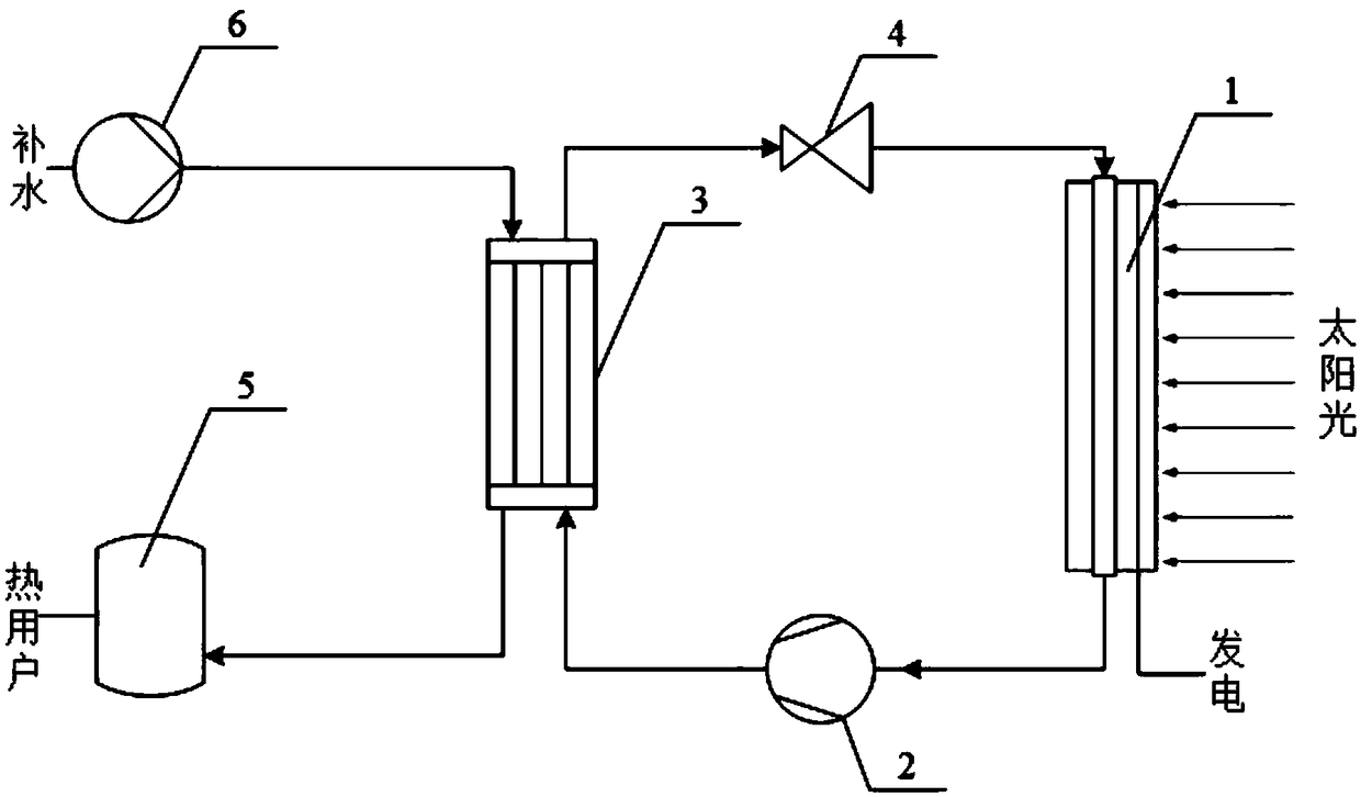
[0018] Such as figure 1 As shown, a thermoelectric coupling utilization solar energy system includes a photovoltaic panel evaporator 1, a compressor 2, a condensation heat exchanger 3, a throttling expansion valve 4, a heat storage tank 5, and a water pump 6; the photovoltaic panel evaporator 1 and the compressor The machine 2, the condensing heat exchanger 3, and the throttling expansion valve 4 are sequentially connected to form a heat pump circulation circuit, and the water pump 6 is connected in series with the condensing heat exchanger 3 and the hot water storage tank 5 to form a hot water passage;

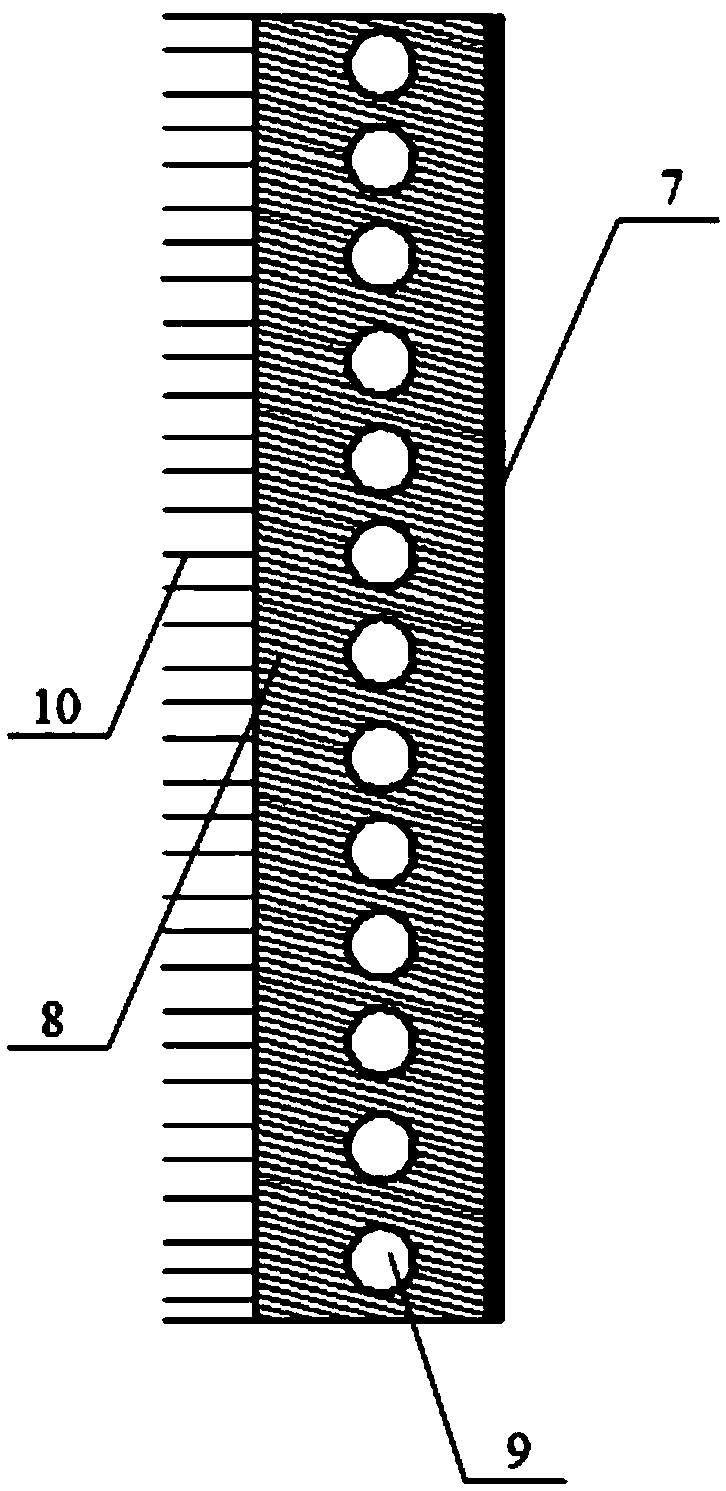
[0019] The photovoltaic panel evaporator 1 includes a solar panel 7, a metal base plate 8, and a working fluid pipeline 9; the metal base plate 8 is closely attached to the solar panel 7, and the inside of the metal base plate 8 is provided with a working fluid pipeline 9, and the inlet and outlet of the working fluid pipeline 9 They are respectively connected with the thrott...


PUM


Abstract

The invention discloses a thermoelectric coupling utilization solar energy system, which includes a photovoltaic panel evaporator, a compressor, a condensation heat exchanger, a throttling expansion valve, a heat storage tank, and a water pump. The photovoltaic panel evaporator includes a solar panel, a metal bottom plate, Working medium pipeline. The photovoltaic panel evaporator is connected in sequence with the compressor, condensing heat exchanger, and throttling expansion valve to form a heat pump cycle, and the water pump, condensing heat exchanger, and heat storage tank are connected in series through the main water pipe to form a hot water passage. The present invention uses the metal bottom plate of the photovoltaic panel directly as the evaporator, utilizes the waste heat of the photovoltaic solar cell to increase the heat exchange temperature of the evaporator, and utilizes the evaporation and heat absorption of the heat pump evaporator, on the one hand, the temperature of the heat pump evaporator is increased, and on the other hand On the one hand, it improves the utilization temperature range of the waste heat of the photovoltaic system, thereby improving the comprehensive utilization efficiency of solar energy, and has a good due prospect.

Description

technical field [0001] The invention relates to solar photovoltaic and heat pump technologies, in particular to a system and method for utilizing solar energy through thermoelectric coupling. Background technique [0002] Solar energy is a kind of renewable energy with abundant reserves. Improving the use of solar energy is of positive significance for reducing the pollution of fossil energy and coping with the global energy crisis. [0003] At present, the utilization of solar energy mainly includes the forms of solar power generation and solar thermal utilization. Solar power mainly adopts two forms of photovoltaic and photothermal. Among them, for the photovoltaic solar power generation system, the photoelectric conversion efficiency is currently only about 20%. Therefore, most of the solar energy is still lost in the form of heat and reflection, and has not been fully utilized effectively. In order to improve the solar energy utilization efficiency of the photovoltaic ...

Claims


Application Information

Patent Timeline
Patent Type & Authority Patents(China)
IPC IPC(8): F25B29/00F25B13/00
CPCF25B13/00F25B29/003F25B27/005
Inventor 张良张晓鹏范利武郑梦莲俞自涛胡亚才
Owner ZHEJIANG TUFF BOILER
Learn More