DC cable connector

A technology of DC cables and shielding layers, applied in cable joints, cable accessories, cable installation, etc., can solve the problems of uneven electric field distribution, electric field distortion at the interface, electric stress concentration, etc., to avoid excessive charge accumulation and reduce electric field. Strength, low cost effect

Inactive Publication Date: 2017-03-08
GLOBAL ENERGY INTERCONNECTION RES INST CO LTD +2
View PDF3 Cites 1 Cited by
  • Summary
  • Abstract
  • Description
  • Claims
  • Application Information

AI Technical Summary

Problems solved by technology

[0004] The breakdown point of the cable joint for high-voltage DC cables generally appears at the end of the high-voltage shielding layer and the root of the stress cone; under the action of high field strength, the space charge in the insulating layer of the joint increases, which will cause the insulating layer of the joint to interact with the insulating layer of the wire. Interfacial charge accumulation, resulting in electric field distortion at the interface, may cause local electric field breakdown
[0005] The existing insulating layer of cable joint joints adopts ordinary silicone rubber insulating material, and its electrical conductivity is lower than that of the cable insulating layer. Under the action of a DC electric field, the field strength distribution in the insulating material is inversely proportional to the electrical conductivity of the material. The field strength of the insulation layer is higher than that of the cable insulation layer. The breakdown field strength of ordinary silicone rubber insulation materials is lower than that of cross-linked polyethylene insulation materials for cables, and it is easy to break down under high DC electric fields.
[0006] The existing stress cone of the cable joint is made of ordinary silicone rubber material. The electrical conductivity of the ordinary silicone rubber material does not change with the field strength of the applied DC electric field, and the electric field distribution cannot be uniform. Under the action of a high DC electric field, electrical stress concentration is easily generated on the stress cone, resulting in stress cone breakdown

Method used


Image

  • DC cable connector
  • DC cable connector
  • DC cable connector

Examples


Embodiment 1

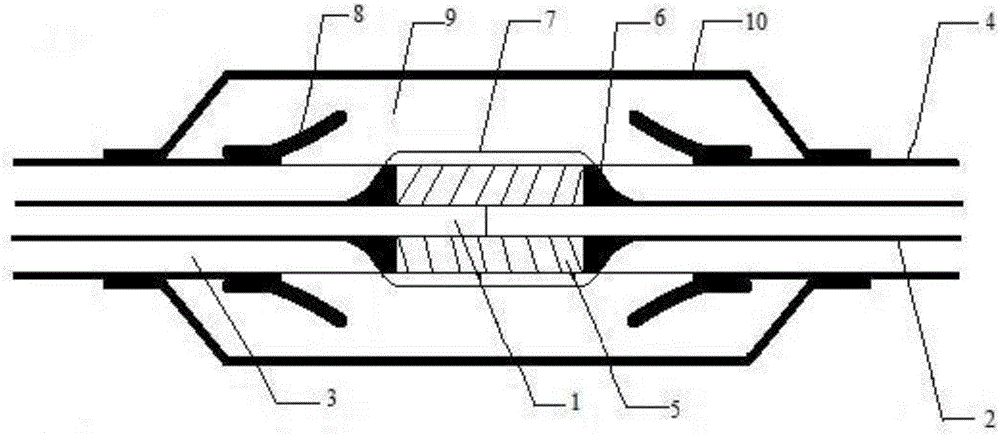
[0052] Such as figure 1 As shown, take the DC cable joint for 320kV XLPE insulated high voltage power cable as an example.

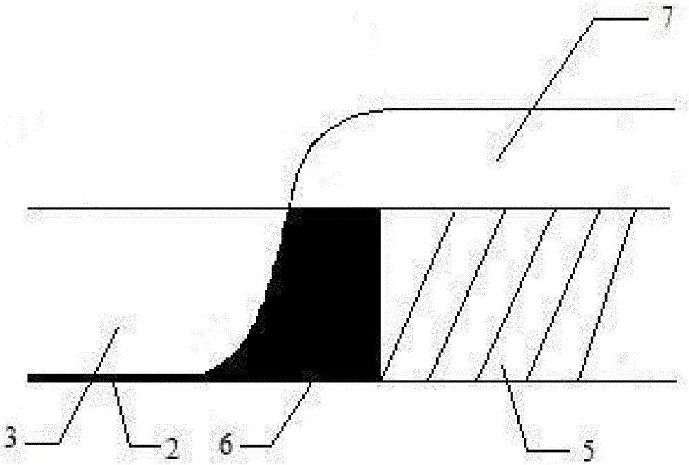
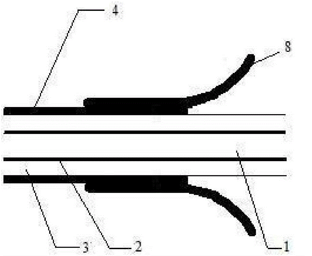
[0053] A DC cable joint, the joint includes a cylindrical high-voltage shielding layer 7, a cylindrical joint insulating layer 9 and a joint shielding layer 10 coaxially arranged in sequence from the inside to the outside, and the joint insulating layers 9 at both ends of the cylindrical high-voltage shielding layer 7 A coaxial symmetrical trumpet-shaped stress cone 8 is embedded on the inner wall, which is symmetrically called two trumpet-shaped symmetry. The trumpet-shaped stress cone 8 includes a cylindrical narrow mouth end and a wide mouth end with a pair of symmetrical arcs in the axial section. The inner wall of the insulating layer 9 is provided with a groove for embedding the narrow end of the stress cone 8 and a protrusion for embedding the high voltage shielding layer 7 .

[0054] The outer diameter of the cylindrical joint insulating layer 9...

Embodiment 2

[0072] Such as figure 1 A DC cable joint is shown, the joint includes a cylindrical high-voltage shielding layer 7, a cylindrical joint insulating layer 9 and a joint shielding layer 10 arranged coaxially from the inside to the outside, and the joint insulation at both ends of the cylindrical high-voltage shielding layer 7 The inner wall of the layer 9 is embedded with a coaxial symmetrical trumpet-shaped stress cone 8, which is symmetrically referred to as two trumpet-shaped symmetry. The trumpet-shaped stress cone 8 includes a cylindrical narrow mouth end and a wide mouth end with a pair of symmetrical arcs in axial section. The inner wall of the joint insulation layer 9 is provided with a groove for embedding the narrow end of the stress cone 8 and a protrusion for embedding the high voltage shielding layer 7 .

[0073] The outer diameter of the cylindrical joint insulating layer 9 is 230 mm, and the two ends of the joint insulating layer 9 are symmetrically arranged circul...

Embodiment 3

[0090] Such as figure 1 A DC cable joint is shown, the joint includes a cylindrical high-voltage shielding layer 7, a cylindrical joint insulating layer 9 and a joint shielding layer 10 arranged coaxially from the inside to the outside, and the joint insulation at both ends of the cylindrical high-voltage shielding layer 7 The inner wall of the layer 9 is embedded with a coaxial symmetrical trumpet-shaped stress cone 8, which is symmetrically referred to as two trumpet-shaped symmetry. The trumpet-shaped stress cone 8 includes a cylindrical narrow mouth end and a wide mouth end with a pair of symmetrical arcs in axial section. The inner wall of the joint insulation layer 9 is provided with a groove for embedding the narrow end of the stress cone 8 and a protrusion for embedding the high voltage shielding layer 7 .

[0091] The outer diameter of the cylindrical joint insulation layer 9 is 200mm, and the two ends of the joint insulation layer 9 are symmetrically arranged round p...


PUM


Abstract

The invention provides a DC cable connector which comprises a cylindrical high voltage shielding layer 7, cylindrical joint insulation layers 9 and a joint shielding layer 10 which are coaxially arranged from inside to outside. Coaxial symmetrical horn-shaped stress cones 8 are embedded to the inner walls of the joint insulation layers 9 of two ends of the cylindrical high voltage shielding layer 7, and two horn openings are symmetrical. Each of the horn-shaped stress cones 8 comprises a cylindrical narrow port end and a wide port end whose axial section is a pair of symmetrical arcs. The inner wall of each of the joint insulation layers 9 is provided with a groove for embedding the narrow ends of the stress cones 8 and a convex block for embedding the high voltage shielding layer 7. According to the DC cable connector, the connector structure design is optimized, the electric field intensity in a stress cone root, a high voltage shielding layer root and the joint insulation layers is reduced, the field intensity distribution in the joint is uniform, and the joint insulation space charge excessive accumulation and electric field breakdown caused by high field intensity are avoided.

Description

technical field [0001] The invention relates to a cable joint, in particular to a DC cable joint. Background technique [0002] Flexible DC transmission is based on voltage source converters, turn-off devices and pulse width modulation. It has the advantages of high controllability, convenient design and construction, small footprint and no communication between converter stations. It has obvious advantages in grid connection, distributed generation grid connection, AC system interconnection, island power supply, and capacity expansion and transformation of urban distribution network. [0003] High-voltage DC cables are an important part of the flexible DC transmission system. The intermediate connector of the cable is an essential device for connecting two cables, and it is also the weak link of the cable system. [0004] The breakdown point of the cable joint for high-voltage DC cables generally appears at the end of the high-voltage shielding layer and the root of the st...

Claims


Application Information

Patent Timeline
Patent Type & Authority Applications(China)
IPC IPC(8): H02G15/08H02G15/188
Inventor 于涛贺之渊尚康良韩正一李文鹏
Owner GLOBAL ENERGY INTERCONNECTION RES INST CO LTD
Why Eureka
Try Eureka