Constant current charging-stopping type charger

A charge-stop, charger technology, applied in the electronic field, can solve the problems of damage, increase the overall scrapping of the charger, and the charging tube is easily damaged.

Inactive Publication Date: 2017-03-15
CHONGQING NINGLAI SCI & TRADE
View PDF4 Cites 0 Cited by
  • Summary
  • Abstract
  • Description
  • Claims
  • Application Information

AI Technical Summary

Problems solved by technology

[0008] The reason for the lack of current products is that there is no constant current and pulse charging circuit, and this circuit has a relatively simple circuit, and can flexibly adjust the relationship between charging and stopping, and the second is that it does not have a limited voltage. A circuit that combines the end of charging (this method is suitable for activated batteries) and the end of timing (this method is suitable for charging non-activated batteries and a large class of batteries such as acid)
The third is that there is no way to use active components for conversion to solve the problem that the charging tube is fragile
If the switch tube is in a pulsed state, it is more likely to become damaged and increase the overall scrapping of the charger

Method used


Image

  • Constant current charging-stopping type charger
  • Constant current charging-stopping type charger
  • Constant current charging-stopping type charger

Examples


Embodiment Construction

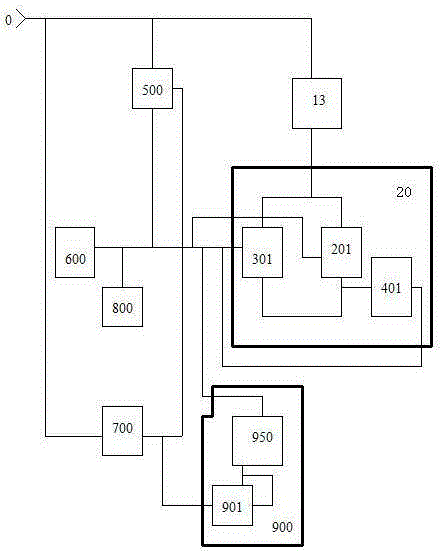
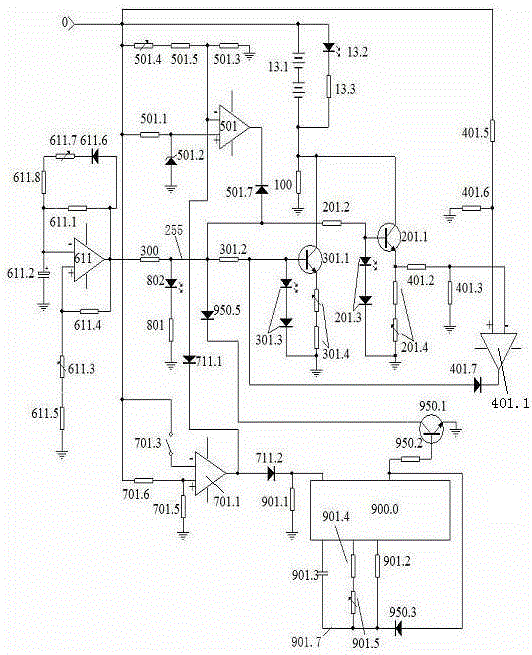
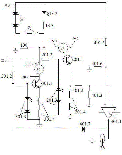
[0100] figure 1 figure 2 image 3 An example of an implementation artifact is given, image 3 Example of detection map in implementation.

[0101] 1. Selection of main components: Computational amplifier, comparison op amp, charging converter, and end switcher are welded with 4 op amps inside an integrated circuit LM324. The transistor in the charging unit is an NPN transistor, the end transistor is 8050, the diode is a surface-bonded diode, the counting oscillation capacitor is a non-polar capacitor, and there is no special requirement for other resistance-capacitance components.

[0102] 2. Make the circuit control board and weld the components: press figure 2 The schematic diagram to make the circuit control board, press figure 2 Schematic of soldered components.

[0103] 3. Power on, check and debug.

[0104] Check that the welding is correct, and then conduct power-on inspection and debugging.

[0105] 1. Check the constant current source part. Check and test se...


PUM


Abstract

The invention provides a constant current charging-stopping type charger, and belongs to the technical field of electronics. The constant current charging-stopping type charger comprises a load unit, a constant current charging unit, a voltage limiting finish unit, a pulse generation unit, a finish switching unit, a charging process display unit and a timing finish unit. Triodes in the constant current charging unit are welded into a constant current form, and are controlled by the pulse generation unit, thus constant current charging in the form of pulses is realized. In the constant current charging unit, the two triodes form a relation of work and backup, and when a triode is damaged, the other triode instantly substitutes, thereby ensuring the life of the charger. Two finish modes are provided, including voltage limiting finish after a battery is fully charged and timing finish by counting, selection is carried out through the finish switching unit, the life of the charger is greatly prolonged, the rejection rate of chargers is reduced, all the units are scientifically connected, comprehensive utilization is achieved, and the reliability is high.

Description

technical field [0001] It belongs to the field of electronic technology. Background technique [0002] With the enrichment of modern life, there are more and more types of electrical appliances using batteries, such as digital machines, mobile phones, etc., and many types of chargers have appeared for this reason, but there are still many types of low-carbon and environmentally friendly charging circuits in these types. exist. [0003] One of its meanings is that in current products, the charging director, which is the circuit transistor that connects and shuts off the charging, is easily damaged. Once damaged, the charger becomes garbage. According to statistics, this failure has become the main failure point of the charger. It is a great waste to turn it into garbage just because of this damage. cost, so people are often throwing away). [0004] The second meaning is that during the charging process, the battery is not charged scientifically, which affects the capacity ...

Claims


Application Information

Patent Timeline
Patent Type & Authority Applications(China)
IPC IPC(8): H02J7/00
Inventor 宁永敭宁永健
Owner CHONGQING NINGLAI SCI & TRADE
Why Eureka
Try Eureka