
A Plasma Synthetic Jet Actuator for High Altitude Vehicles

A plasma and synthetic jet technology, applied in the direction of plasma, electrical components, etc., can solve the problems of gas path organization and flow control effect, failure to achieve plasma synthetic jet, effective work of jet actuator, etc., to improve uniformity and momentum exchange ability, improve flow uniformity and momentum exchange ability, and broaden the effect of flow control range

Active Publication Date: 2018-07-27
NANJING UNIV OF AERONAUTICS & ASTRONAUTICS
View PDF4 Cites 0 Cited by
  • Summary
  • Abstract
  • Description
  • Claims
  • Application Information

AI Technical Summary

Problems solved by technology

However, glow discharge cannot quickly heat the gas in the cavity and eject high-speed airflow in a short period of time, which completely fails to meet the needs of plasma synthetic jets, and loses the advantages of this control method itself.
Therefore, conventional plasma synthetic jet exciters designed according to standard atmospheric pressure cannot work effectively at high altitude and low pressure, and the exciter must be redesigned according to the atmospheric conditions in the cruising state
[0004] On the other hand, in the traditional boundary layer jet control method, the outlet form of the jet also has a very significant impact on the gas path organization of the jet and the flow control effect
However, in the literature and materials published about this new type of flow control method using plasma, it usually adopts the form of a single circular hole or a single straight slit, which will make the control range of the jet very limited, only at the jet outlet. A small area nearby can achieve better control effect, so it is necessary to design a more efficient jet outlet form by referring to the traditional boundary layer jet control method

Method used


Image

  • A Plasma Synthetic Jet Actuator for High Altitude Vehicles
  • A Plasma Synthetic Jet Actuator for High Altitude Vehicles
  • A Plasma Synthetic Jet Actuator for High Altitude Vehicles

Examples


Embodiment Construction

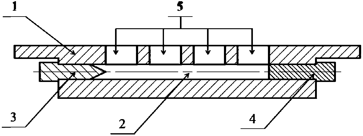
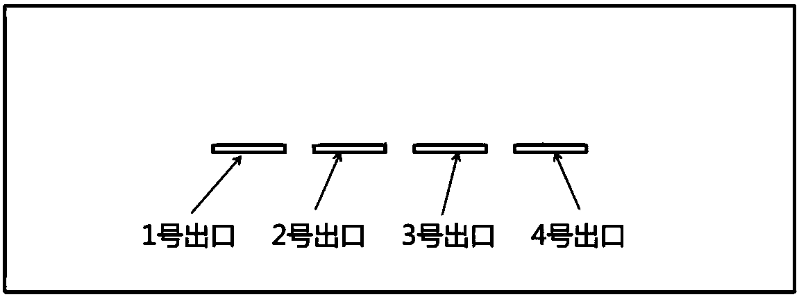
[0017] see figure 1 and figure 2 Shown, be that the present invention is used for a kind of high-altitude aircraft plasma synthetic jet exciter, comprise exciter body 1, cathode discharge electrode 3, anode discharge electrode 4, cathode discharge electrode 3, anode discharge electrode 4 external high-voltage pulse power supply (not shown icon). The exciter body 1 is provided with through holes 2 passing through both ends of the exciter body. The cathode discharge electrode 3 and the anode discharge electrode 4 are made of tungsten copper alloy. The upper surface of the exciter body 1 is also provided with several air release grooves 5 communicating with the through holes. The cathode discharge electrode 3 is inserted and fixed at one end of the through hole 2 , while the anode discharge electrode 4 is inserted and fixed at the other end of the through hole 2 . The cathode discharge electrode 3, the anode discharge electrode 4 and the through hole 2 are sealed with high t...


PUM


Abstract

The invention discloses a plasma synthetic jet exciter for high-altitude aircraft. It includes an exciter body, a discharge chamber, a cathode discharge electrode, an anode discharge electrode, and a multi-slit jet outlet. When working, the discharge electrodes connected to both sides of the exciter cavity break down the air and discharge, the gas in the discharge cavity is instantly heated, and flows out from the jet outlet on the upper surface of the exciter body to form a high-speed jet. The invention is especially aimed at high-altitude and high-speed aircraft, and utilizes the discharge characteristic that the breakdown voltage drops rapidly under low pressure to extend the distance between the electrodes of the plasma synthetic jet actuator, and the spark discharge is still maintained between the electrodes, thereby expanding the flow control range of the actuator. At the same time, the jet outlet is arranged with multiple straight slits parallel to the discharge arc, which is conducive to injecting momentum and energy into a wider range of gases. The invention is particularly suitable for large-scale flow control in high-altitude and high-speed aircraft, and has good engineering application prospects.

Description

technical field [0001] The invention relates to the field of plasma flow control. Background technique [0002] In 2003, the Johns Hopkins University Applied Physics Laboratory proposed a plasma synthetic jet actuator as a new type of flow control technology. The exciter consists of an insulated cavity with a built-in cathode and anode and a small outflow hole on the upper surface of the cavity. The working principle of the plasma synthetic jet exciter is as follows: the anode and the cathode are respectively connected to the positive and negative electrodes of the high-voltage pulse power supply. When the power supply is running, the pressure and temperature of the air in the nearly airtight cavity rise rapidly due to the electrode discharge, and the high-pressure and high-temperature gas flows through the small outflow hole to form a jet. As an active flow control technology, this technology does not require an additional gas source. It has fast response, no mechanical m...

Claims


Application Information

Patent Timeline
Patent Type & Authority Patents(China)
IPC IPC(8): H05H1/48
CPCH05H1/48H05H1/47
Inventor 谭慧俊张宇超孙姝何小明程林
Owner NANJING UNIV OF AERONAUTICS & ASTRONAUTICS
Learn More