Liquid source supply device

A technology of supply device and liquid source, applied in gas/liquid distribution and storage, pipeline system, mechanical equipment, etc., can solve the problems of potential pollution, vacuum pump damage, waste, etc., achieve low emission value, avoid pollution, and reduce workload Effect

Pending Publication Date: 2017-03-29
PNC PROCESS SYSTEMS CO LTD
View PDF10 Cites 4 Cited by
  • Summary
  • Abstract
  • Description
  • Claims
  • Application Information

AI Technical Summary

Problems solved by technology

[0006] First, the structure of the connecting pipe of the source bottle is complicated, and there are many dead ends in the tee, so it is easy to leave a certain amount of liquid source. Usually, this kind of liquid source has a high viscosity, and it is difficult to purge and replace this part of the liquid source in the dead end. When the source bottle is disassembled When the pipe is connected, the residual liquid source reacts with the air to cause certain hazards
[0007] Second, the vacuum pump directly extracts the liquid source in the connecting pipe of the source bottle, and a large amount of liquid source vapor vaporized by vacuum is discharged into the exhaust gas processor instantaneously, which may instantaneously exceed the rated processing capacity of the exhaust gas processor, resulting in unqualified exhaust gas discharge, which is harmful to personnel and Atmospheric safety and pollution hazards
[0008] Third, the liquid source in the connecting pipe of the whole source bottle is discharged into the exhaust gas processor for treatment, and usually this liquid source medium is very expensive, resulting in waste
[0009] Fourth, due to the flammability and explosive risks of liquid sources, an explosion-proof dry vacuum pump is required, which is expensive; and the vacuum pump is a moving part of a mechanical operation, and maintenance and maintenance are complicated
[0010] Fifth, the vacuum pump usually requires the inlet pressure to be less than 1 bar. Improper operation will cause the exhaust pressure of the panel to far exceed 1 bar, thus causing the risk of damage to the vacuum pump

Method used


Image

  • Liquid source supply device

Examples


Embodiment Construction

[0032] The following will clearly and completely describe the technical solutions in the embodiments of the present invention with reference to the accompanying drawings in the embodiments of the present invention. Obviously, the described embodiments are only some, not all, embodiments of the present invention. Based on the embodiments of the present invention, all other embodiments obtained by persons of ordinary skill in the art without making creative efforts belong to the protection scope of the present invention.

[0033] The core of the present invention is to provide a liquid source supply device, which can avoid leakage and is safe and stable to use.

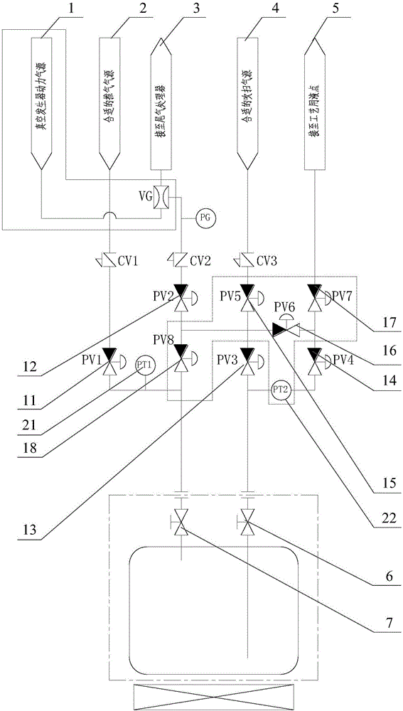
[0034] Please refer to figure 1 , figure 1 It is a connection structure diagram of a liquid source supply device provided by the present invention.

[0035] A liquid source supply device provided by the present invention includes a bottle mouth valve group arranged at the bottle mouth of the liquid source container, a...


PUM


Abstract

The invention discloses a liquid source supply device, comprising a bottleneck valve bank arranged at the bottleneck of a liquid source container, wherein the bottleneck valve bank comprises a gas phase interface valve and a liquid phase interface valve, the gas phase interface valve is connected with a pushing gas source by a first valve body, the gas phase interface valve is connected with a tail gas treatment device by a second valve body, and a vacuum generator device is arranged between the second valve body and the tail gas treatment device; the liquid phase interface valve is connected with a purging gas source by a third valve body, and the liquid phase interface valve is connected with a process fluid outlet by a fourth valve body; one end, close to the bottleneck valve bank, of the second valve body is connected to one end, far away from the bottleneck valve bank, of the third valve body. Purging gas can press a liquid source in a pipe back into the container, the second valve body is connected to the gas phase interface valve at the bottleneck of the liquid source container, and gas pressure of the upper part in the container can be relieved by the gas phase interface valve, so the work load of the tail gas treatment device is greatly lowered, and less tail gas can be completely and effectively treated away, has a lower emission value, and is safer and more environment-friendly, thus avoiding forming pollution.

Description

technical field [0001] The invention relates to the technical field of chemical manufacturing, and more specifically relates to a liquid source supply device. Background technique [0002] Toxic and harmful chemical liquid sources are used in semiconductor / photovoltaic solar / fiber optics and other pan-manufacturing industries. Usually, the liquid source container and bottle mouth valve assembly are connected to the supply panel as a whole and then purged, replaced and supplied to form a complete liquid source. Supply device. Among them, this kind of chemical liquid source has a certain viscosity, and it will react violently or explode when it comes into contact with air or water. Ensuring absolute safety when replacing and installing the source bottle is the basis of the entire supply system. [0003] The supply panel is integrally connected to the liquid source container and the bottle mouth valve assembly through the source bottle connecting pipe (Pigtail). Every time the...

Claims


Application Information

Patent Timeline
Patent Type & Authority Applications(China)
IPC IPC(8): F17D1/12F17D5/00
CPCF17D1/12F17D5/00
Inventor 连海洲吴海华薛元
Owner PNC PROCESS SYSTEMS CO LTD
Why Eureka
Try Eureka