
Multiband matching circuit, radio frequency circuit, antenna system and mobile terminal

A matching circuit and antenna system technology, applied in antennas, transmission systems, electrical components, etc., can solve the problems of difficult matching circuit debugging and design, RF circuits occupying too much circuit board layout space, etc., to save layout space and reduce the number of , the effect of simple circuit structure

Inactive Publication Date: 2017-04-19
QINGDAO HISENSE MOBILE COMM TECH CO LTD
View PDF4 Cites 18 Cited by
  • Summary
  • Abstract
  • Description
  • Claims
  • Application Information

AI Technical Summary

Problems solved by technology

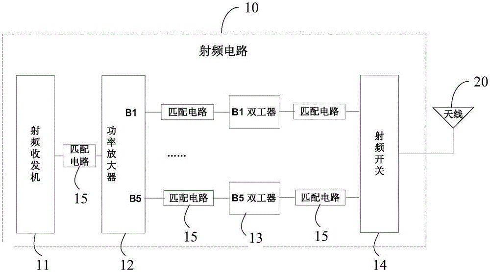
Further, if the mobile terminal will support multiple operating frequency bands, in the radio frequency circuit 10, for the radio frequency signal of each frequency band output by the power amplifier 12, a corresponding radio frequency transmission circuit will be set at the output of the power amplifier 12; Yes, for different RF transmission circuits, since the actual impedance of each device is different, it is necessary to set up different matching circuits for each RF transmission circuit. Under the current trend of increasing available operating frequency bands of mobile terminals, this not only gives matching circuits Difficulty in debugging design, and the RF circuit takes up too much circuit board layout space

Method used


Image

  • Multiband matching circuit, radio frequency circuit, antenna system and mobile terminal
  • Multiband matching circuit, radio frequency circuit, antenna system and mobile terminal
  • Multiband matching circuit, radio frequency circuit, antenna system and mobile terminal

Examples


Embodiment Construction

[0027] Reference will now be made in detail to the exemplary embodiments, examples of which are illustrated in the accompanying drawings. When the following description refers to the accompanying drawings, the same numerals in different drawings refer to the same or similar elements unless otherwise indicated. The implementations described in the following exemplary examples do not represent all implementations consistent with the present invention. Rather, they are merely examples of apparatuses and methods consistent with aspects of the invention as recited in the appended claims.

[0028] In the existing technology, with the rapid development of mobile communication technology, the available working frequency band of mobile terminals increases, resulting in more matching circuits, increasing the difficulty and time of debugging, and increasing the space occupied by radio frequency circuit boards , the embodiment of the present invention provides a multi-band matching circu...


PUM


Abstract

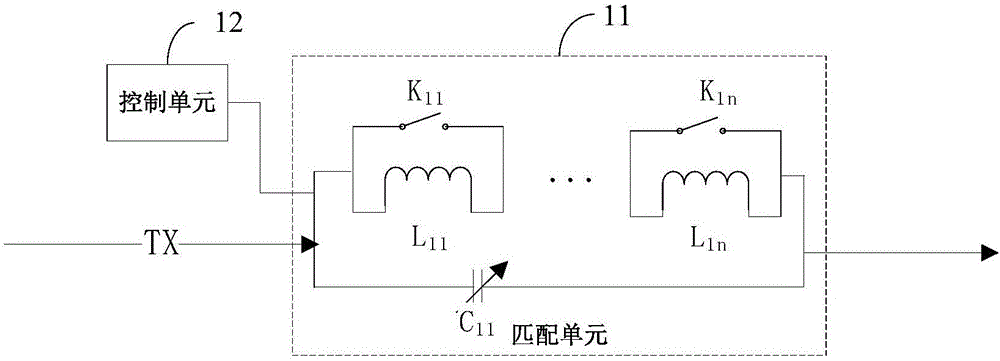
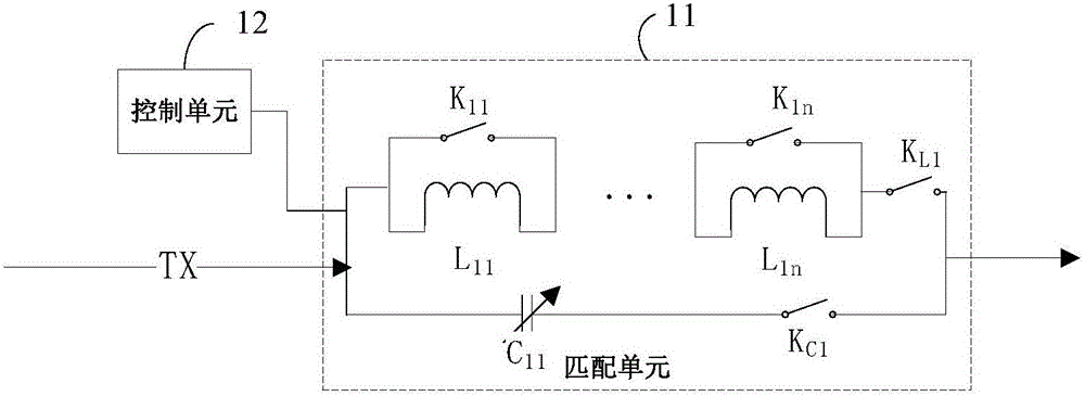
The invention relates to a multiband matching circuit, a radio frequency circuit, an antenna system and a mobile terminal. Specifically, the matching circuit is designed into the structure of an adjustable capacitor and an inductor group which are connected in parallel, wherein the inductor group comprises at least one inductors which are connected in series in turn, and one switch is connected in parallel on each inductor. Meanwhile, a program control unit is also arranged in the matching circuit. The capacitance value of the adjustable capacitor can be controlled and different switches can be selected through the program control unit so that different capacitor and inductor combination forms can be realized, and free adjustment of the capacitance and induction values in the circuit can be realized. With application of the matching circuit, the requirements of characteristic impedance of different transmission lines can be adapted by adjusting the circuit parameters of the matching circuit in the debugging and use process of the radio frequency circuit, and performance debugging of multiple bands can be realized on one set of matching circuit so that the debugging difficulty can be reduced, the number of the matching circuits in the radio frequency circuit can be reduced, the circuit structure is simple and the laying space of the circuit board can be saved.

Description

technical field [0001] The invention relates to the technical field of mobile communication, in particular to a multi-band matching circuit, a radio frequency circuit, an antenna system and a mobile terminal. Background technique [0002] At present, the communication function of a mobile terminal is mainly realized by its internal antenna system, wherein the core components of the antenna system include an antenna and a radio frequency transceiver. In the communication process, the antenna converts the radio frequency signal from the radio frequency transceiver into electromagnetic waves radiated into space to complete the transmission of wireless communication signals, or the antenna converts the electromagnetic waves propagating in space into radio frequency signals and feeds them back to the radio frequency transceiver. To complete the reception of wireless communication signals. [0003] figure 1 It is a schematic diagram of the antenna system structure of the mobile ...

Claims


Application Information

Patent Timeline
IPC IPC(8): H03H5/00H01Q23/00H04B1/40
CPCH03H5/006H01Q23/00H04B1/40
Inventor 武国强王国涛
Owner QINGDAO HISENSE MOBILE COMM TECH CO LTD
Learn More