Closed-loop control circuit for power switching device and method

A power switching device and closed-loop control circuit technology, applied in the field of power electronics, can solve the problems of high power consumption and slow speed, and achieve the effects of reducing turn-off loss, speeding up turn-off speed, and reducing gate drive current.

Inactive Publication Date: 2017-04-19
HUAZHONG UNIV OF SCI & TECH
View PDF2 Cites 9 Cited by
  • Summary
  • Abstract
  • Description
  • Claims
  • Application Information

AI Technical Summary

Problems solved by technology

The present invention aims to solve the problem of large power consumption and slow speed in the prior art due to the use of an open-loop

Method used


Image

  • Closed-loop control circuit for power switching device and method
  • Closed-loop control circuit for power switching device and method
  • Closed-loop control circuit for power switching device and method

Examples


Embodiment Construction

[0026] In order to make the object, technical solution and advantages of the present invention clearer, the present invention will be further described in detail below in conjunction with the accompanying drawings and embodiments. It should be understood that the specific embodiments described here are only used to explain the present invention, not to limit the present invention.

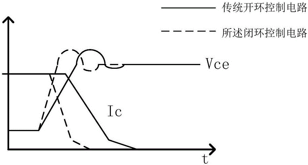
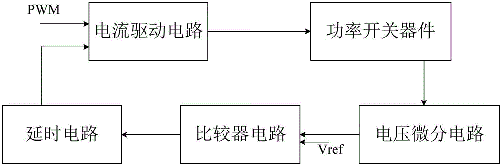
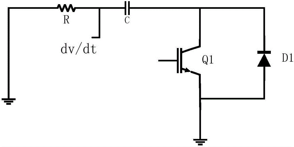
[0027] In order to solve the problems of slow speed and high power consumption of the traditional open-loop control circuit of the aforementioned power switching device, the present invention provides a closed-loop control circuit that directly controls the driving current by using the current source mode. And the delay circuit realizes the closed-loop real-time control of the gate-level driving current, and divides the whole turn-off process into three stages. In the first stage, the maximum allowable current of the device is used for driving to speed up the turn-off speed. In the second stage, th...


PUM


Abstract

The invention discloses a closed-loop control circuit for a power switching device and a method. The closed-loop control circuit comprises a voltage differential circuit, a comparator circuit, a delay circuit and a current driving circuit, wherein the first input end of the comparator circuit is connected with the output end of the voltage differential circuit; the second input end of the comparator circuit is used for being connected with reference voltage; the input end of the delay circuit is connected with the output end of the comparator circuit; the first input end of the current driving circuit is connected with the output end of the delay circuit; the second input end of the current driving circuit receives PWM signals; and the output end of the current driving circuit is connected with the control end of the power switching device. A voltage change rate dv/dt signal is detected through the differential circuit, when the dv/dt signal is larger than the reference voltage, the current driving circuit is controlled, instantaneous current is provided, gate driving current is reduced, and the voltage overshoot is maintained to be unchanged basically. The driving circuit can be accurately controlled to output voltage and current, the turn-off speed is quickened, and the turn-off loss is reduced.

Description

technical field [0001] The invention belongs to the field of power electronics, and more specifically relates to a closed-loop control circuit and method for a power switching device. Background technique [0002] Power switching devices are widely used in various power electronic devices. Each power switching device needs a driver chip to drive it. The traditional driver chip uses an open-loop control circuit, which cannot realize real-time gate drive current through a feedback loop. control. [0003] The traditional control circuit adopts open-loop control and uses a voltage-type structure. By adjusting the gate-level resistance R g to control the switching speed. reduce R g , can increase the gate current of the device, speed up the switching speed, and reduce the switching loss, but at the same time, it will cause an increase in voltage overshoot, bring about electromagnetic interference (EMI) problems, and even cause overvoltage damage to the device; increasing R g ...

Claims


Application Information

Patent Timeline
IPC IPC(8): H03K17/04H03K17/042H03K17/567
CPCH03K17/0406H03K17/042H03K17/567H03K2217/0036
Inventor 童乔凌徐俊王涛严逸婷张侨闵闰吕典
Owner HUAZHONG UNIV OF SCI & TECH
Why Eureka
Try Eureka