Slurry reactor methanol synthesis process

A methanol synthesis and slurry bed technology, which is applied in the preparation of hydroxyl compounds, the preparation of organic compounds, the separation/purification of hydroxyl compounds, etc., can solve the problems that the catalyst cannot be replaced online, the economic benefits of the device are affected, and the inert solvent is easily entrained. Achieve the effects of avoiding economic losses, reducing engineering investment and device energy consumption, and reducing bed temperature

Active Publication Date: 2017-04-26
SINOPEC NINGBO ENG +2
View PDF3 Cites 0 Cited by
  • Summary
  • Abstract
  • Description
  • Claims
  • Application Information

AI Technical Summary

Problems solved by technology

The reaction heat removal of this technology is lagging behind, the reaction temperature is high, the single-pass conversion rate is low, and the inert solvent is easily entrained to the downstream; moreover, the catalyst cannot be replaced online, and the device must be shut down when the catalyst is replaced, which affects the economic benefit of the device

Method used


Image

  • Slurry reactor methanol synthesis process
  • Slurry reactor methanol synthesis process
  • Slurry reactor methanol synthesis process

Examples


Embodiment 2

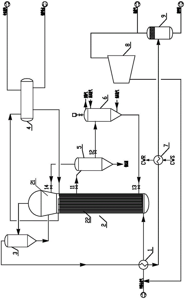
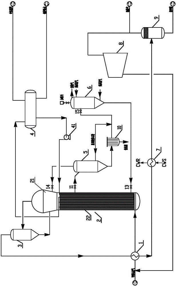
[0047] Such as figure 2 As shown, in the present embodiment, when the catalyst needs to be replaced, the slurry extraction pipeline root valve 11 on the upper part of the slurry bed reactor reaction zone 22, the gas phase return pipeline cut-off valve 14 of the cross-flow filter 5, and the catalyst filter 10 and the catalyst filter 10 are opened. The cut-off valve 15 of the inert solvent connection pipeline between the preparation tanks 6.

[0048] The slurry in the upper part of the reaction zone 22 is introduced into the cross-flow filter 5, and the slurry is initially filtered and concentrated; the gas contained in the slurry and the synthesis gas produced by the new reaction are returned to the slurry bed reactor from the top of the cross-flow filter 5 In the gas phase space 21 of 2, the inert solvent filtered out enters the catalyst preparation tank 6 relying on the pressure difference; the catalyst slurry concentrated by the cross-flow filter 6 enters the filter 10 for ...

Embodiment 1

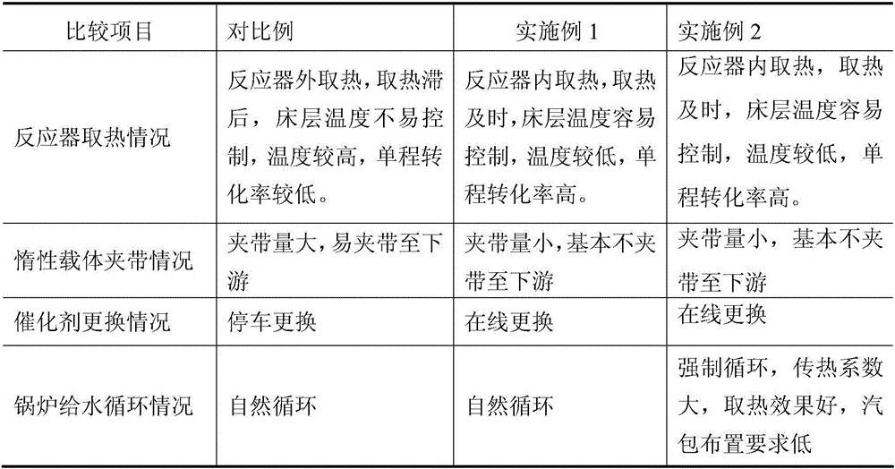
[0054] The comparison of embodiment 1 and embodiment 2 and comparative example is shown in table 1.

[0055] Table 1

[0056]

[0057] As can be seen from Table 1, in the slurry bed methanol synthesis process provided by the present invention, the reactor takes heat in a timely manner, the bed temperature is stable and easy to control, the single-pass conversion rate is high, and the circulating gas volume is small, which greatly reduces engineering investment and equipment. Energy consumption; the amount of inert carrier entrainment is small, basically no entrainment to the downstream; the catalyst is replaced online, which avoids the economic loss of parking due to catalyst replacement.


PUM

PropertyMeasurementUnit
particle diameteraaaaaaaaaa
quality scoreaaaaaaaaaa

Abstract

The invention relates to a slurry reactor methanol synthesis process. The slurry reactor methanol synthesis process is characterized by comprising the following steps: mixing raw material gas from upstream with circulating gas to form mixed gas, enabling the mixed gas to enter a shell side of the reactor from the bottom after heat exchange to be in contact with a catalyst in the shell side to perform reaction; enabling bubble point boiler water to enter a tube side of the reactor; discharging the reaction gas generated by the reaction out of the top of the reactor and enabling the reaction gas to enter a separator to perform separation; enabling the separated non-gas phase to return to the reactor from the gas phase space at the upper part of the reactor, enabling the separated gas phase, namely crude methanol synthesis gas, to enter a gas liquid separator after heat exchange, pressurizing the separated gas phase to serve as circulating gas, wherein the separated liquid phase is crude methanol; when catalyst abrasion reaches to a set value, extracting catalyst slurry from the reactor; supplementing fresh catalyst slurry into the shell side of the reactor. According to the slurry reactor methanol synthesis process, the catalyst can be changed timely without shutdown.

Description

technical field [0001] The invention relates to a methanol synthesis process, in particular to a slurry bed methanol synthesis process. Background technique [0002] At present, the production of methanol from coal and natural gas at home and abroad basically adopts the gas-solid phase catalytic method. Since methanol synthesis is a strong exothermic reaction process, the gas-solid phase catalytic reactor is limited by heat transfer. Poor adaptability, the content of CO in the reaction gas at the inlet of the reactor has to be controlled at a relatively low level, generally no more than 16%, and the conversion rate of the synthesis gas once passed through the reactor is not high, so the content of methanol in the outlet gas is correspondingly low. A large amount of unreacted gas must be recycled, which consumes a lot of power. [0003] Slurry bed technology is used for methanol synthesis. The reactor contains three phases of gas, liquid and solid. Synthesis gas is reacted t...

Claims


Application Information

Patent Timeline
Patent Type & Authority Applications(China)
IPC IPC(8): C07C31/04C07C29/76C07C29/152
CPCC07C29/152C07C29/76C07C31/04
Inventor 卢新军许仁春徐洁亢万忠李宁黄剑平周金路张志国涂林
Owner SINOPEC NINGBO ENG
Why Eureka
Try Eureka