
In-site measurement system of aspheric die and measurement method and measurement examination method of system

A measurement system and aspheric surface technology, applied in the direction of measuring devices, instruments, optical devices, etc., can solve the problems that the measurement accuracy needs to be improved, the processing of the shearing interferogram is complex, and the in-situ measurement accuracy cannot reach the nanometer level, etc., to achieve real-time High effect of in-situ measurement, measurement accuracy and stability

Inactive Publication Date: 2017-04-26
ZHEJIANG UNIVERSITY OF SCIENCE AND TECHNOLOGY
View PDF3 Cites 10 Cited by
  • Summary
  • Abstract
  • Description
  • Claims
  • Application Information

AI Technical Summary

Problems solved by technology

Shear interferometry does not require a standard reference wave surface, and can flexibly measure aspheric surfaces of various shapes, but it has the following disadvantages when used in in-situ measurement: 1) Due to the harsh requirements of interference on the environment, the measurement process should avoid environmental vibrations and noise interference, which is difficult to achieve on machine tools; 2) The measurement accuracy needs to be improved. For high-precision micro-aspheric molds, the in-situ measurement accuracy of the existing shear interferometer cannot reach the nanometer level; 3) the shear The processing of the tangential interferogram is relatively complicated, which restricts the real-time performance of the on-site measurement to a certain extent

Method used


Image

  • In-site measurement system of aspheric die and measurement method and measurement examination method of system
  • In-site measurement system of aspheric die and measurement method and measurement examination method of system

Examples


Embodiment Construction

[0036] The present invention will be described in further detail below in conjunction with the accompanying drawings, but it is not intended to limit the protection scope of the present invention.

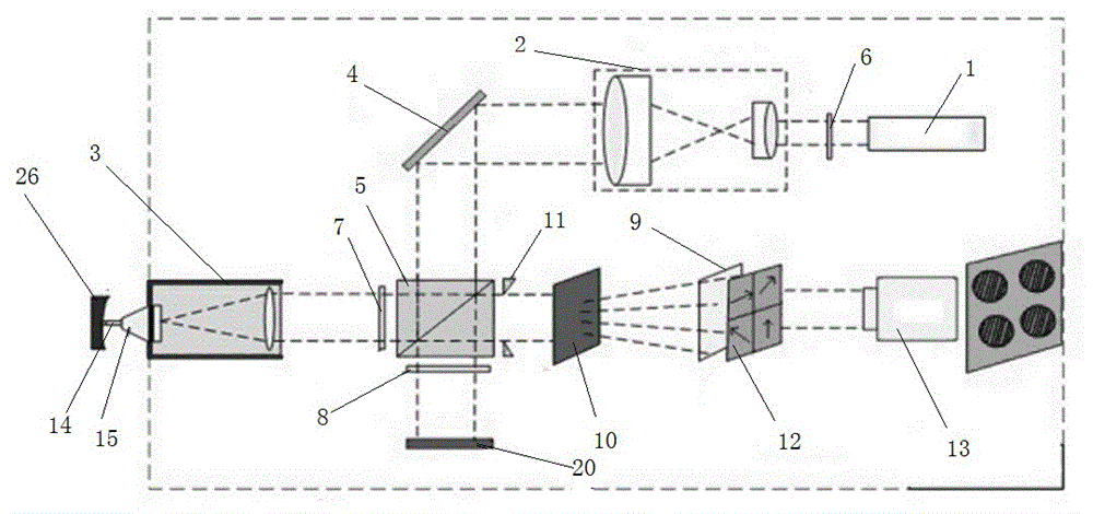
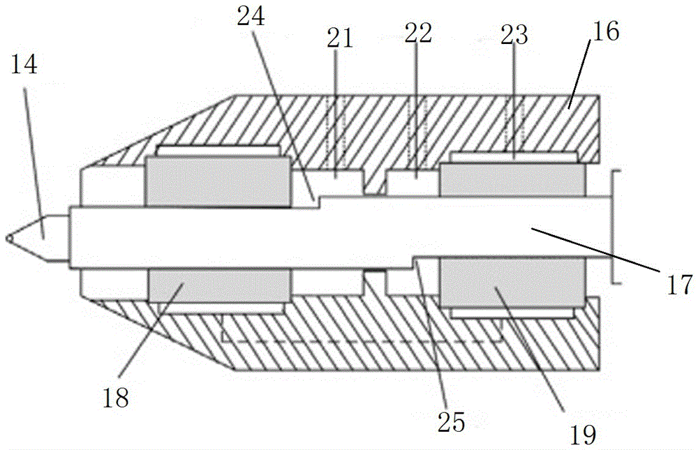
[0037] Such as figure 1 and 2 As shown, an in-situ measurement system for a hybrid aspheric lens mold includes a contact probe 14, an air bearing 15, an optical interference system, an image acquisition and processing system, and a software processing system. The optical interference system includes: semiconductor laser 1, laser beam expander system 2, cat's eye mirror 3, mirror 4, reference mirror 20, polarization beam splitter 5, 1 / 2λ wave plate 6, beam splitting grating 10, spatial filter 11 And polarizer set 12 and three 1 / 4λ glass slides. The image acquisition and processing system includes: CCD camera, image acquisition card and computer, and the software processing system includes: phase calculation module, surface coordinate conversion module, surface fitting module and e...


PUM

PropertyMeasurementUnit
Wavelengthaaaaaaaaaa

Abstract

The invention discloses an in-site measurement system of an aspheric die. The system comprises a contact probe, an air-floatation bearing, an optical interference system, an image collecting and processing system and software processing system; the optical interference system comprises a light source, a laser beam expanding system, an cat eye reflector, two reflectors, a polarized spectroscope, a 1 / 2 lambda wave plate, three 1 / 4 lambda wave plates, a beam splitting grating or a holographic beam splitting unit, a space filter and a Polaroid group; the image collecting and processing system comprises a CCD camera, an image collection card and a computer; and the software processing system comprises a phase calculation module, a surface coordinate conversion module, a curved surface fitting module and an error analysis module. The system and methods thereof have the advantages that the displacement measuring precision can reach the nanometer magnitude, real-time in-site measurement can be realized, interference of vibration noises can be avoided in the measurement process, and the measuring accuracy and stability are high.

Description

technical field [0001] The invention relates to a three-dimensional measurement device based on optical interference technology, in particular to an in-situ measurement system of an aspheric mold, a measurement method and a measurement inspection method thereof. Background technique [0002] At present, the lenses of various camera devices have been developed towards thinner and shorter, and tiny aspheric lenses (with a diameter of several millimeters to tens of microns) have become the main force of this development trend. According to the statistics of the Taiwan Optoelectronics Technology Industry Association (PIDA), based on the calculation that a digital camera needs to be equipped with 1 to 3 aspheric molded glass lenses, in 2007, there were about 230 million aspheric molded glass lenses on the digital camera. Demand, the world's aspherical molded glass lens production value accounts for about 19% of the world's optical components production, aspheric molded glass lens...

Claims


Application Information

Patent Timeline
IPC IPC(8): G01B11/00G01B11/24
CPCG01B11/00G01B11/2441
Inventor 朱勇建曹胜范玉峰王宇
Owner ZHEJIANG UNIVERSITY OF SCIENCE AND TECHNOLOGY
Learn More