Slab laser module with wave-front distortion self-correction ability

A wavefront distortion, laser module technology, applied in lasers, laser parts, phonon exciters, etc., can solve problems such as difficult to achieve the fill factor of the slat medium, system instability, thermal management and optical path design defects

Active Publication Date: 2017-04-26
NAVAL AERONAUTICAL & ASTRONAUTICAL UNIV PLA +1
View PDF5 Cites 6 Cited by
  • Summary
  • Abstract
  • Description
  • Claims
  • Application Information

AI Technical Summary

Problems solved by technology

To avoid beam splitting, the spot size in the thickness direction of the slab is further limited
In order to obtain high-power laser output, the width ratio of the slab medium is larger than the thickness, which leads to the laser beam emitted by the laser and the amplifier using the CCEPS laser module as a slender strip-shaped spot, and the complexity of the optical system
For example, when using adaptive optics technology for active control of beam quality, multiple cylindrical lenses must be used to shape the spot, which not only increases the complexity of the system structure, but also increases the difficulty of adjustment
[0007] 2. Due to the small size of the laser beam in the thickness direction, when the laser beam is transmitted once in the slab laser module, the filling factor inside the slab medium is difficult to reach 1
[0008] 3. In the CCEPS module, the pump light is incident from the end cut at 45°, and the heat sink cannot effectively cool the area
However, the high-speed flow of coolant can easily cause structural vibration, resulting in system instability, and water pressure can cause deformation of quartz glass, resulting in static wavefront distortion
[0012] 3. There is a contradiction between heat dissipation and improving system efficiency: in order to take away the heat in the medium as soon as possible, the slab medium is required to be as thin as possible, which will reduce the absorption length of the pump light and reduce the pump efficiency
[0014] In engineering practice, researchers found that lasers and amplifiers based on slab laser media are difficult to achieve high beam quality laser output
It is mainly manifested in two aspects: First, there is thermally induced wavefront distortion in the width direction (perpendicular to the direction of the ZigZag plane) and thickness direction (parallel to the direction of the ZigZag plane), and the focal length of the thermal lens in the two directions is inconsistent. , the thermal effect in the width direction cannot be effectively compensated, and the beam quality is even worse; second, there are many high-frequency components in the wavefront distortion. High beam quality laser output
In addition, when the laser module is determined, the magnitude of the thermally induced wavefront distortion increases with the increase of the output power, which may cause the problem that the magnitude of the wavefront distortion exceeds the correction capability of the deformable mirror under high power conditions
[0015] In summary, both CCEPS and ThinZag slab laser modules have certain defects in thermal management and optical path design

Method used


Image

  • Slab laser module with wave-front distortion self-correction ability
  • Slab laser module with wave-front distortion self-correction ability
  • Slab laser module with wave-front distortion self-correction ability

Examples


specific Embodiment 1

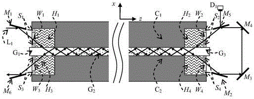
[0089] It is generally believed that the ZigZag optical path can reduce the adverse effects of uneven pump light intensity, temperature and stress in the thickness direction (X) and length direction (Z) of the average slab medium in the ZigZag plane (XOZ plane), and weaken the beam section (XOY section ) in the wavefront distortion in the thickness direction (X) of the slab. The research shows that the ZigZag optical path cannot completely eliminate the thermally induced wavefront distortion in the thickness direction of the slab, and its offset effect on the thermal effect is related to the temperature field distribution in the slab medium and the number of reflections of the laser inside the slab. When the temperature field distribution in the slab medium is determined, with the increase of the number of reflections of the oscillating laser inside the slab medium, the waveform of the thermally induced wavefront distortion transforms between "M" and "W" types (as shown in Figu...

specific Embodiment 2

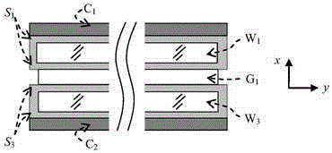
[0125] In the direction perpendicular to the ZigZag optical path (that is, the slab width direction, Y direction), the ZigZag optical path cannot eliminate thermally induced wavefront distortion, which is why the beam quality in the width direction of the slab laser is worse than that in the thickness direction. Further research shows that even if the heat sink is uniformly pumped in the width direction of the slab and the heat sink is uniformly dissipated in the width direction of the slab (the heat dissipation coefficient is a constant value), since the size of the heat sink in the Y direction is larger than that of the slab, It will still cause the center temperature of the slab medium to be high and the edge temperature to be low in the width direction, resulting in wavefront distortion. Therefore, using the combination of side pumping and end pumping, the edge temperature of the slab in the side pumping module is high and the center temperature is low, resulting in a "V"-s...

specific Embodiment 3

[0135] Fig. 6(a) and Fig. 6(b) are the sectional views along the length direction and along the width direction of the slat laser module of Embodiment 3 of the present invention, respectively;

[0136] Fig. 7(a) and Fig. 7(b) are cross-sectional views along the length direction and the width direction of the slat medium according to Embodiment 3 of the present invention, respectively;

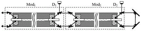
[0137] The working principle of specific embodiment 3 is similar to that of specific embodiments 1 and 2, the difference is that in the slab laser module shown in Figure 6 (a), Figure 6 (b), Figure 7 (a), and Figure 7 (b), The laser reflection device includes a first reflection mirror M 1 and rectangular reflectors M 7 ;

[0138] The first mirror M 1 and rectangular reflectors M 7 Placed at both ends of any pair of diagonal corners of the slat medium;

[0139] Incident laser L 1 through the first mirror M 1 Reflected into the slab medium, right-angle reflective prism M 7 Receives the in...


PUM


Abstract

The invention provides a slab laser module with wave-front distortion self-correction ability through optimizing thermal management and optical path design. The slab laser module comprises a laser reflection device and a slab medium used as a gain medium. The upper and lower surfaces at the two ends of the slab medium are evanescent-membrane-free areas, and the middle part between the upper and lower surfaces is an evanescent membrane area. Incident laser L1 enters the inside of the slab medium from the evanescent-membrane-free area at one end of the slab medium, is transmitted along the length direction of the slab medium, and goes out from the evanescent-membrane-free area at the other end of the slab medium. The laser reflection device reflects the output incident laser L1 into the slab medium for second transmission, and the incident laser L1 goes out from the incidence end of first transmission. The constraint condition for the point-of-incidence position of second transmission of the incident laser L1 is that the wave-front distortion waveform generated when the incident laser L1 passes through the slab medium for the first time and the wave-front distortion waveform generated when the incident laser L1 passes through the slab medium for the second time are opposite. Thus, output laser featuring no wave-front distortion, high power and high beam quality is obtained.

Description

technical field [0001] The invention belongs to the technical field of slab lasers and laser amplifiers, in particular to a slab laser module with wavefront distortion self-correction capability. Background technique [0002] Obtaining laser output with high power and high beam quality has always been the goal pursued by researchers of solid-state lasers. A key issue in achieving high power and high beam quality at the same time is how to effectively manage the heat of the solid-state laser medium. The connotation of thermal management includes three aspects: reducing the generation of waste heat, efficiently dissipating heat, and compensating for the adverse effects of thermal effects. [0003] Compared with traditional rod-shaped media, slab-shaped laser media have outstanding advantages such as large cooling surface, zigzag optical path transmission can greatly reduce the adverse effects of thermal effects, etc., and are highly valued by the high-energy laser community. ...

Claims


Application Information

Patent Timeline
Patent Type & Authority Applications(China)
IPC IPC(8): H01S3/042H01S3/09H01S3/10H01S3/105
CPCH01S3/042H01S3/09H01S3/10H01S3/105
Inventor 刘亮黄秀军周一鸣赵爽杨宁虎徐红艳宋镇江石德乐张彬
Owner NAVAL AERONAUTICAL & ASTRONAUTICAL UNIV PLA
Why Eureka
Try Eureka