Defect detection method and system applied to receiver

A defect detection and receiver technology, applied in electrical components and other directions, can solve the problems of difficult to meet the long-term development of enterprises, difficulty in quality inspection of vibration parts, and low efficiency of manual inspection, so as to improve the detection efficiency and accuracy, and facilitate expansion and application. Effect

Inactive Publication Date: 2017-04-26
PHICOMM (SHANGHAI) CO LTD
View PDF4 Cites 5 Cited by
  • Summary
  • Abstract
  • Description
  • Claims
  • Application Information

AI Technical Summary

Problems solved by technology

[0005] The above two solutions solve some problems in the prior art from different angles, but none of them involves the detection process of the receiver in the production process, and the detection process is also very important as the last process in the production process. Among them, the quality detection of the vibration part is the most difficult
In the prior art, the quality inspection of the vibration part of the receiver mainly adopts the method of manual inspection. By placing the vibration plate voice coil face up in the turnover box, the defective products are eliminated. According to the defective phenomenon of the vibration plate, it is fed back to In the previous manufacturing process, process improvement, manual inspection is not only inefficient, but also has low detection accuracy, so it is difficult to meet the long-term development of the enterprise
Moreover, it takes about 20 seconds to manually detect the defects of the receiver winding and voice coil coating, and the correct detection rate is only about 96%, and it is often impossible to accurately measure the defect area and find out the production problem.

Method used


Image

  • Defect detection method and system applied to receiver
  • Defect detection method and system applied to receiver
  • Defect detection method and system applied to receiver

Examples


Embodiment 1

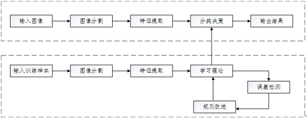
[0052] like figure 1 As shown, the defect detection method applied to the receiver of the present invention comprises the following steps:

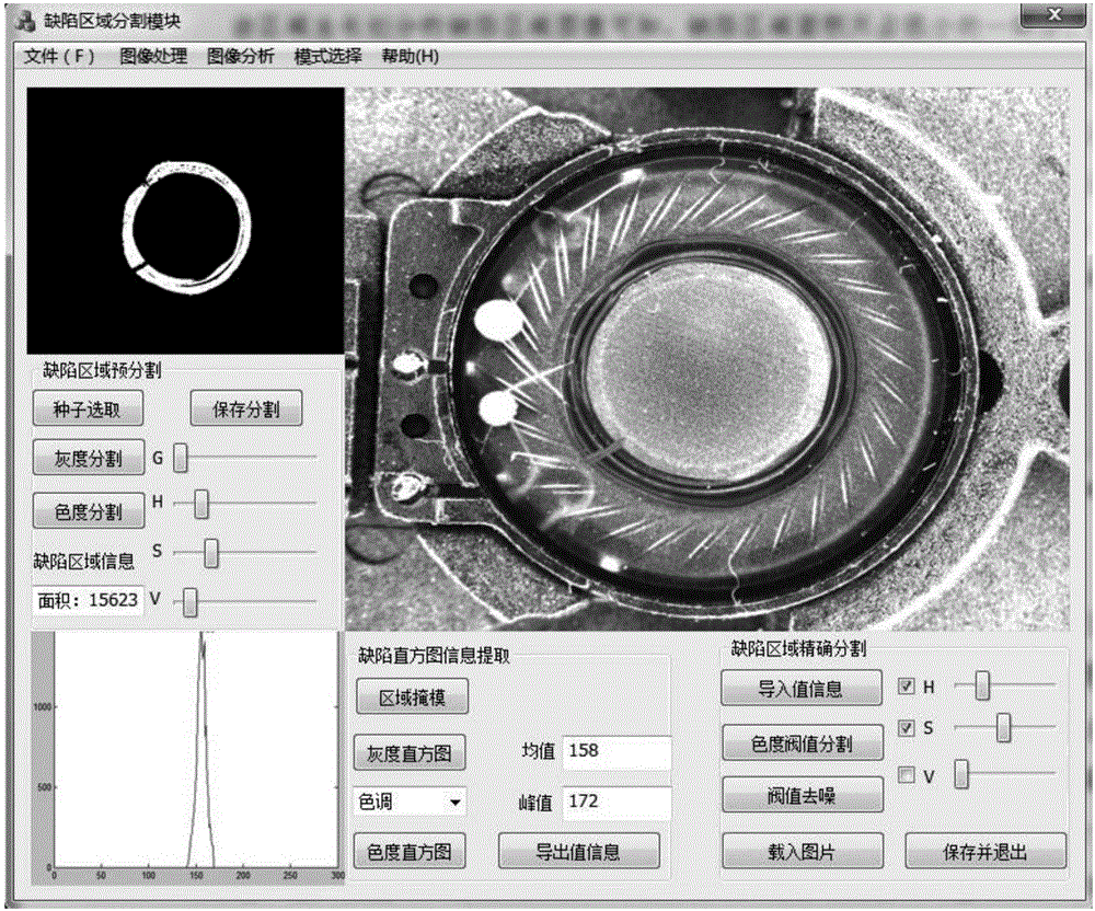
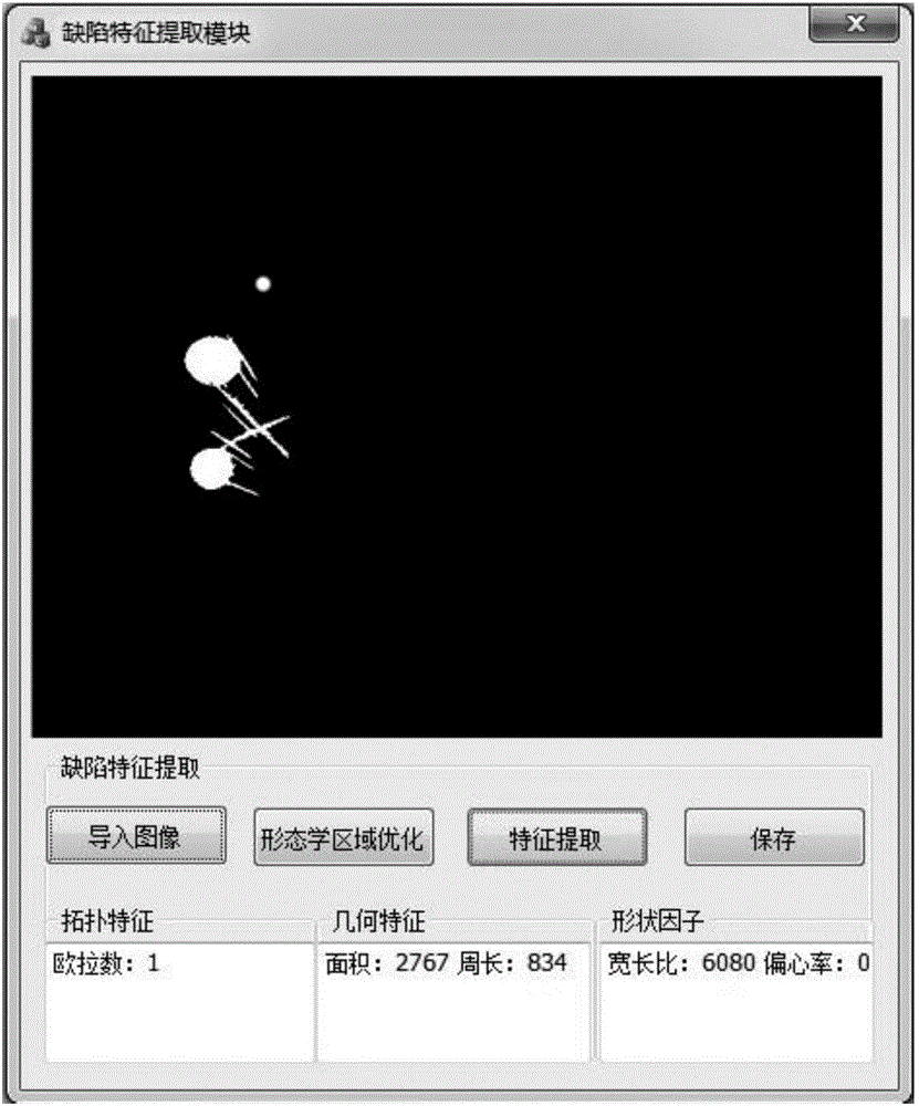
[0053] like figure 2 As shown, step S1: Defect area segmentation: input training samples through a debugging module 121, and then conduct any one or more of the receiver winding, voice coil coating, notched copper wire, and voice coil lead wire in the training sample. Segmentation to obtain the defect area, and in order to obtain complete data and realize the purpose of comprehensively detecting the receiver, the winding wire, voice coil coating, notched copper wire and voice coil lead wire of this embodiment are all subjected to defect segmentation;

[0054] Further, in step S1, the method for obtaining the defect area includes the following steps:

[0055] S1.1: Color image pre-segmentation and training: select seed growth points for region segmentation through manual interaction;

[0056] The specific method of selecting the seed g...

Embodiment 2

[0089] This embodiment is similar to Embodiment 1, the difference is:

[0090] In this embodiment, the defect region segmentation module 122, the defect feature extraction module 123 and the debugging module 121 in the online inspection system 1 are the defect region segmentation module 122, the defect feature extraction module 123 and the debugging module 121 in the offline debugging system 2, Wherein the classification identification module 14 and the defect target identification module 24 are connected by wireless and / or wired mode, in the online mode, start each module of the online detection system 1, and start each module of the offline debugging system 2 in the offline mode, At the same time, the data including the classification criteria obtained in the offline mode can be directly used in the detection in the online mode. Similarly, the detection data information collected in the online mode can be directly used in the offline mode as reference information for building...

Embodiment 3

[0092] This embodiment is similar to Embodiment 2, the difference is that:

[0093] The defect object identification module 24 and the classification identification module 14 of this embodiment are integrated in the same module, which further simplifies the system architecture.

[0094] The present invention mainly has two operating modes, which are offline debugging mode and online detection mode. In the offline debugging mode, image segmentation, feature extraction and recognition operations can be performed on images, and neural network training can be performed on the extracted features. Through continuous The optimal training result is obtained through training, so as to be used for online detection; in the online detection mode, the defect of the receiver can be detected in real time on the assembly line, and the production process can be accelerated; and the present invention mainly performs application verification for the three types of area defects of the receiver, fu...


PUM


Abstract

The invention relates to a defect detection method and system applied to a receiver. The method comprises steps that S1, defect area segmentation, a training sample is inputted through a debugging module, and area segmentation for the training sample is carried out to acquire defect areas; S2, defect characteristic extraction, a defect characteristic description method based on characteristic descriptors is utilized to carry out characteristic extraction of characteristics of the defect areas according to the defect areas acquired in the step S1; S3, defect target identification, the defect characteristics are utilized, BP neural network training is carried out through sample and parameter selection to acquire classification rules; and S4, online detection, pictures are acquired from a production line at each time interval, the classification rules are utilized to discriminate the acquired pictures in real time to acquire a detection result, and the data information including the yield data in each production process is further collected. The method is advantaged in that not only can detection efficiency is improved, but also production conditions are mastered integrally, production can be improved through utilizing the acquired detection information, and enterprise revenue is improved.

Description

technical field [0001] The invention belongs to the text input technology of electronic equipment, in particular to a defect detection method and system applied to a receiver. Background technique [0002] The receiver is mainly composed of three parts: the vibration part, the magnetic circuit part, and the cavity part. Its production includes the manufacture of the vibration part, the manufacture of the magnetic circuit part and the assembly of the cavity. Each part includes multiple manufacturing processes. The structure of the receiver itself, the production process and the final testing process will have an impact on the performance and pass rate of the receiver. Therefore, in order to achieve a high pass rate, the structure of the receiver must be optimized. Production process and Improve detection efficiency and accuracy. [0003] In order to achieve the above technical problems, people have carried out long-term exploration. For example, a Chinese patent discloses a ...

Claims


Application Information

Patent Timeline
Patent Type & Authority Applications(China)
IPC IPC(8): H04R29/00
CPCH04R29/00H04R2420/05
Inventor 廖武
Owner PHICOMM (SHANGHAI) CO LTD
Why Eureka
Try Eureka