Magnetohydrodynamic gyroscope

A technology of magnetohydrodynamics and gyroscopes, which is applied in the aviation field, can solve the problems of life limitation, complex processing technology of liquid floating gyroscopes and electrostatic gyroscopes, and the inability of gyroscopes to overcome contact wear, and achieve broad application prospects and excellent performance. Excellent, lightweight effect

Inactive Publication Date: 2017-05-03
于平
View PDF0 Cites 1 Cited by
  • Summary
  • Abstract
  • Description
  • Claims
  • Application Information

AI Technical Summary

Problems solved by technology

However, there are many problems in existing gyroscopes: precession-based dynamic tuning gyroscopes have insurmountable contact wear, liquid floating gyroscopes and electrostatic gyroscopes have complicated manufacturing processes; optical gyroscopes based on int

Method used


Image

  • Magnetohydrodynamic gyroscope

Examples


Embodiment Construction

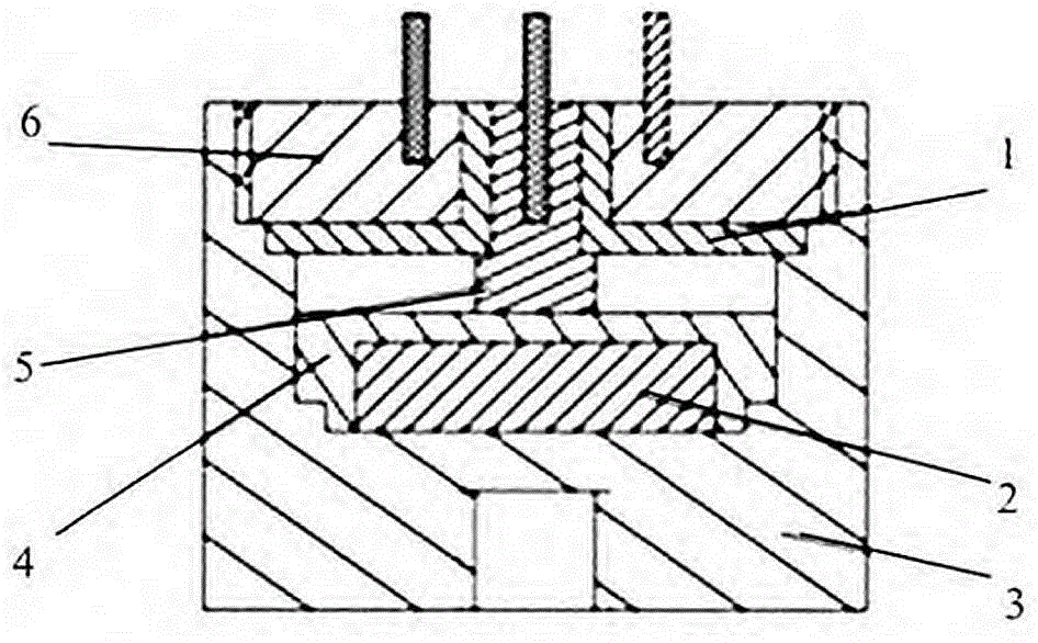
[0012] The present invention will be further described below in conjunction with drawings and embodiments.

[0013] Such as figure 1 , MHD gyroscope utilizes the conductive properties of magnetic fluid materials, and its basic idea is the principle of electromagnetic induction. The lower cylinder is a permanent magnet, which produces a vertical magnetic field; the upper ring is a magnetic fluid channel with a small viscosity. Fix it together with the rotating object to be measured. When an angular velocity is generated, since the viscosity of the magnetic fluid is very small, it hardly moves relative to the fixed inertial coordinate system, so a relative velocity will be generated between the magnetic fluid and the permanent magnet v , the magnetic fluid cuts the magnetic force lines, thus generating a motional electromotive force E between the inner and outer wall electrodes.

[0014] The magnetic hydrodynamic gyroscope includes three parts: the construction of the magneti...


PUM


Abstract

A magnetohydrodynamic gyroscope comprises three parts of construction of a magnetofluid channel, a vertical magnetic circuit and a magnetic field shield cover. The defect of mechanical wear in a conventional gyroscope and the defect that the life of an optical gyroscope is limited by optical devices are overcome, and the magnetohydrodynamic gyroscope has characteristics of high precision, wide band and long life. Furthermore, the magnetohydrodynamic gyroscope can resist impact and is small in size and light in weight. The gyroscope appears excellent in inertial navigation and has bright application prospects in the fields of satellite micro-angle vibration measurement and north finding.

Description

technical field [0001] The invention relates to a magnetohydrodynamic gyroscope, which is suitable for the aviation field. Background technique [0002] The gyroscope is the most important component with the highest technical content in inertial navigation. It is used to detect the angular motion of the carrier. Its comprehensive performance directly determines the overall performance of the inertial navigation system. However, there are many problems in existing gyroscopes: precession-based dynamic tuning gyroscopes have insurmountable contact wear, liquid floating gyroscopes and electrostatic gyroscopes have complex manufacturing and processing techniques; optical gyroscopes based on interference... Limitations of optical devices; the accuracy of MEMS gyroscopes based on the Coriolis effect is difficult to improve. Although the processing and manufacturing technology of gyroscopes has reached a high level, whether it is traditional mechanical gyroscopes or optical, MEMS a...

Claims


Application Information

Patent Timeline
IPC IPC(8): G01C19/00
CPCG01C19/00
Inventor 于平
Owner 于平
Why Eureka
Try Eureka