Composite thermal interface material of orientated pored graphene foam and low-melting-point alloy

A technology of graphene foam and thermal interface materials, applied in the field of thermally conductive materials, can solve problems such as long thermal conduction paths, unfavorable thermal conductivity, and large thermal resistance

Inactive Publication Date: 2017-05-17
CHINA EPRI ELECTRIC POWER ENG CO LTD +1
View PDF4 Cites 8 Cited by
  • Summary
  • Abstract
  • Description
  • Claims
  • Application Information

AI Technical Summary

Problems solved by technology

In addition, ordinary porous materials have high thermal resistance, and the internal pores are randomly distri

Method used


Image

  • Composite thermal interface material of orientated pored graphene foam and low-melting-point alloy

Examples


example 1

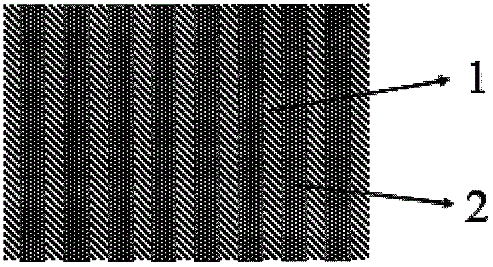
[0010] The composite thermal interface material provided in this embodiment is composed of a graphene foam with directional pores and a low melting point alloy, and the low melting point alloy is uniformly filled in the pores of the graphene foam. The directional holes of the graphene foam are parallel to the heat transfer direction, and the pore size is 1300 microns. The low melting point alloy is an indium-bismuth-tin-gallium alloy with a mass ratio of In100Bi66Sn33Ga1.2 and a melting point of 63°C. The thermal conductivity of the above composite thermal interface material was tested on the Longwin TIM LW-9389 steady state heat flow thermal conductivity tester (Taiwan Ruiling Technology Co., Ltd.). When the test temperature is 30℃, the thermal conductivity is 8W / (m·k) ); When the test temperature is 70℃, the thermal conductivity is 36W / (m·k).

example 2

[0012] The composite thermal interface material provided in this embodiment is composed of a graphene foam with directional pores and a low melting point alloy, and the low melting point alloy is uniformly filled in the pores of the graphene foam. The directional holes of the graphene foam are parallel to the heat transfer direction, and the pore size is 1300 microns. The low melting point alloy is an indium-bismuth-tin-gallium alloy with a mass ratio of In100Bi62Sn31Ga16 and a melting point of 47°C. The thermal conductivity of the composite thermal interface material was tested on the Longwin TIM LW-9389 steady-state heat flow thermal conductivity tester (Taiwan Ruiling Technology Co., Ltd.). When the test temperature is 30℃, the thermal conductivity is 13W / (m·k) ); When the test temperature is 60℃, the thermal conductivity is 42W / (m·k).

example 3

[0014] The composite thermal interface material provided in this embodiment is composed of a graphene foam with directional pores and a low melting point alloy, and the low melting point alloy is uniformly filled in the pores of the graphene foam. The directional holes of the graphene foam are parallel to the heat transfer direction, and the pore size is 700 microns. The low melting point alloy is an indium-bismuth-tin-gallium alloy with a mass ratio of In100Bi66Sn33Ga1.2 and a melting point of 63°C. The thermal conductivity of the above composite thermal interface material was tested on the Longwin TIM LW-9389 steady-state heat flow thermal conductivity tester (Taiwan Ruiling Technology Co., Ltd.). When the test temperature is 30℃, the thermal conductivity is 5W / (m·k) ); When the test temperature is 70℃, the thermal conductivity is 32W / (m·k).


PUM

PropertyMeasurementUnit
Thermal conductivityaaaaaaaaaa
Apertureaaaaaaaaaa
Thermal conductivityaaaaaaaaaa

Abstract

The invention provides a composite thermal interface material of orientated pored graphene foams and a low-melting-point alloy. At normal temperature, the low-melting-point alloy exists in pores of the graphene foams in a solid manner; at working temperature, the low-melting-point alloy is molten and filled into pores of heat conduction interfaces, and the low-melting-point alloy can be prevented from overflowing by the graphene foams; the low-melting-point alloy is an indium-bismuth-tin-gallium alloy; the melting point of the low-melting-point alloy is within 40-70 DEG C; the graphene foams are of a pored structure parallel to a heat conduction direction. After the low-melting-point alloy is filled, the heat conductivity in the heat conduction direction can be greatly improved.

Description

Technical field [0001] The invention relates to the field of thermal conductive materials, in particular to a composite thermal interface material of oriented hole graphene foam and low melting point alloy. Background technique [0002] With the development of electronic devices in the direction of miniaturization and miniaturization, and the increasing integration of electronic chips, the working efficiency and reliability of electronic devices are increasingly dependent on the solution of heat dissipation problems, so the heat dissipation of electronic packaging has become more and more important. importance. The heat dissipation problem is particularly prominent for high-power devices, such as high-power diode lasers, high-brightness light-emitting diodes, and high-power sensors. These sensors generate a lot of heat when they work and require the use of thermal interface materials with high thermal conductivity. Quickly and effectively transmit to the outside environment via ...

Claims


Application Information

Patent Timeline
IPC IPC(8): C09K5/14
CPCC09K5/14
Inventor 查鲲鹏朱海涛王梦婕周建辉王航吴大雄雷清泉
Owner CHINA EPRI ELECTRIC POWER ENG CO LTD
Why Eureka
Try Eureka