Melting slag waste heat recovery system

A waste heat recovery system and molten slag technology, applied in waste heat treatment, lighting and heating equipment, furnace components, etc., can solve the requirements that the working life is difficult to meet the requirements of use, the bearing is difficult to bear, and the working life of the rotating cup is difficult to meet the requirements of use And other issues

Active Publication Date: 2017-05-17
徐州企润食品有限公司
View PDF7 Cites 7 Cited by
  • Summary
  • Abstract
  • Description
  • Claims
  • Application Information

AI Technical Summary

Problems solved by technology

Problems existing in the waste heat recovery process of rotary cup granulation slag ① Due to the high rotation speed of the rotary cup body of the rotary cup granulation method, which is 1000-3000r / min, industrial bearings are difficult to withstand under high temperature, high speed and harsh environments. Life is difficult to meet the requirements of use
② Due to the direct contact of the rotating cup with high-temperature slag, the structure of the rotating cup and the limitation of the slag granulation process, the cooling of the rotating cup body is difficult to solve, and the working life of the rotating cup is difficult to meet the requirements of use, and it has not yet been industrialized. application

Method used


Image

  • Melting slag waste heat recovery system
  • Melting slag waste heat recovery system
  • Melting slag waste heat recovery system

Examples


Embodiment Construction

[0121] Below in conjunction with accompanying drawing and embodiment the present invention will be further described:

[0122] Reference attached Figure 1-36 :

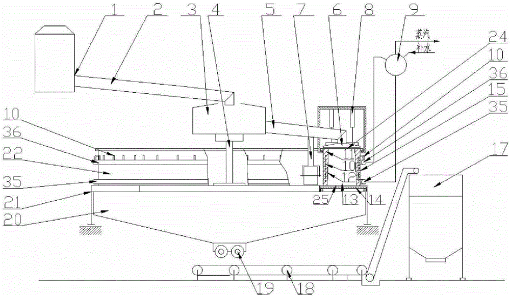
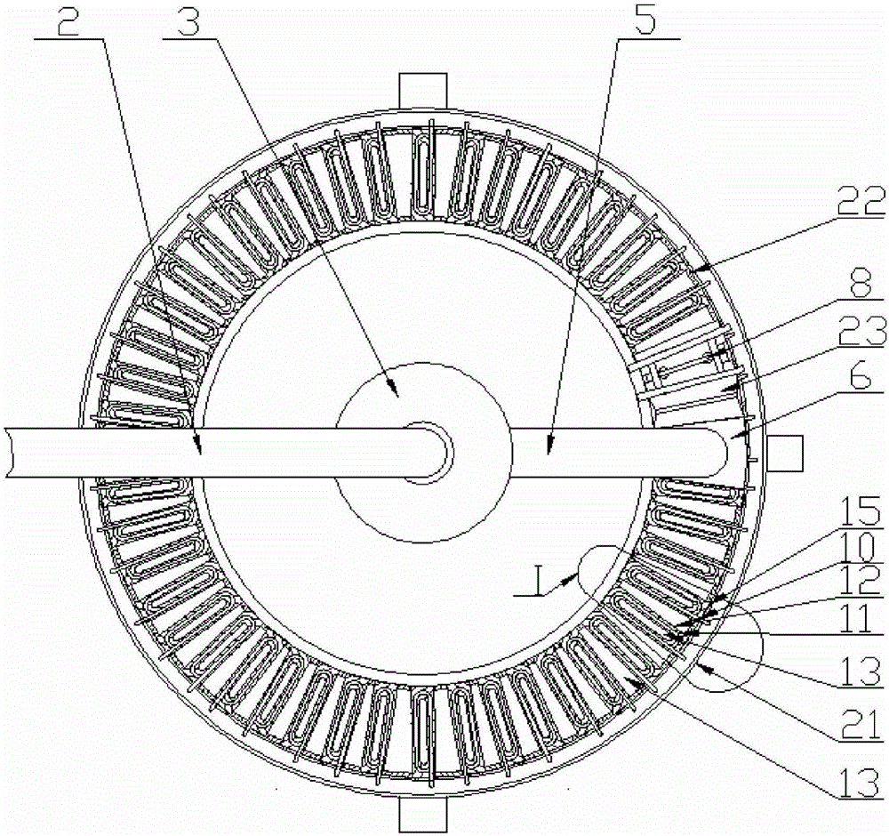
[0123] The system includes a slag feeding system, a slag heat exchange device 22 and a steam water system;

[0124] The slag heat exchange device 22 is composed of at least one heat exchange unit 15;

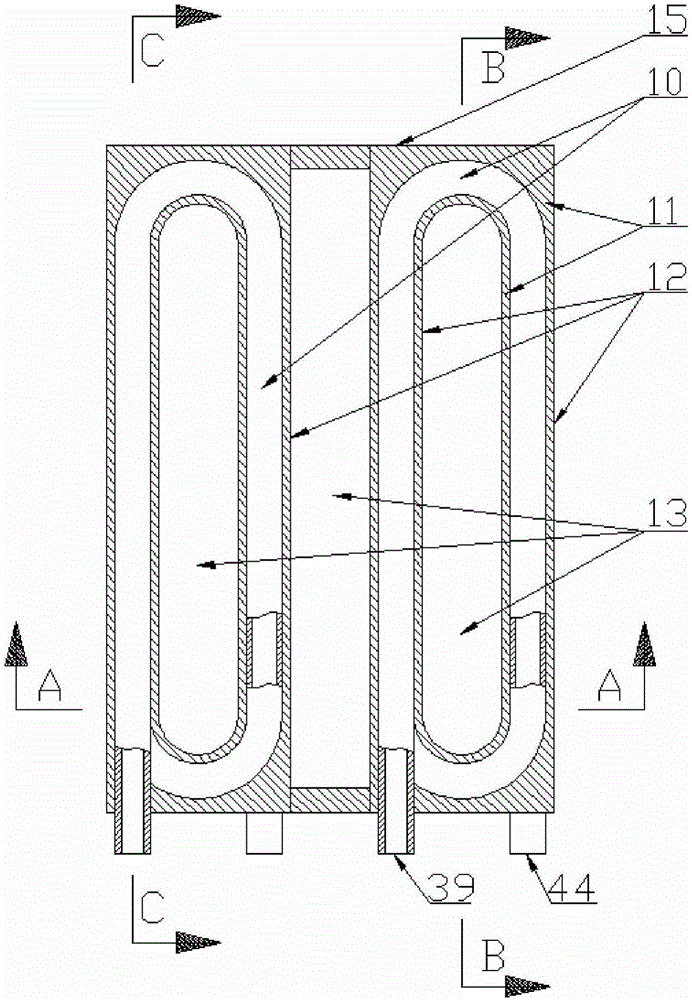
[0125] The heat exchange unit 15 is selected from one of the following four structures:

[0126] 151: A cylinder-shaped slag heat exchange chamber 13 surrounded by slag heat exchange plates 12 and slag baffles 14. The upper and lower parts of the slag heat exchange chamber 13 are the upper feed port 24 and the lower feed port 25, respectively. A slag baffle 14 is arranged below the feed port 25;

[0127] 152: An airtight cavity is formed by the pressure-bearing shell 42, the upper end plate 40 of the shell and the lower end plate 43 of the shell. The water inlet 44 and the water outlet 39 are arranged on the cavity...


PUM


Abstract

The invention discloses a melting slag waste heat recovery system. The melting slag waste heat recovery system comprises a melting slag feeding system, a melting slag heat exchanging device and a vapor-water system. The melting slag heat exchanging device is composed of at least one heat exchanging unit. Each exchanging unit adopts one of four structures, specifically, a melting slag injector is arranged at the output end of the melting slag feeding system, and the melting slag injector is arranged above an upper material opening; the melting slag heat exchanging device and the melting slag heat exchanging system are of moving type structures or static type structures according to practical requirements; when the vapor-water system is matched with the melting slag heat exchanging device of the static type structure, the vapor-water system is composed of a water inlet pipe connector, a water inlet pipe, a water outlet pipe connector and a water outlet pipe; and when the vapor-water system is matched with the melting slag heat exchanging device of the moving type structure, the vapor-water system is composed of the water inlet pipe connector, the water inlet pipe, the water outlet pipe connector, the water outlet pipe and a pressure resistant deformable pipe or a rotating joint. The melting slag waste heat recovery system has the advantages of simple and reasonable in structure, compact in arrangement, small in occupied area, low in investment, high in waste heat recovery rate and the like.

Description

technical field [0001] The invention relates to a waste heat recovery system device, in particular to a molten slag waste heat recovery system for steel mill blast furnace slag and converter slag. Background technique [0002] At present, about 300kg of blast furnace slag is produced for every ton of pig iron produced by the blast furnace of a steel plant. The temperature of the newly discharged slag is about 1500°C. One ton of blast furnace slag contains about 1700MJ of heat, which is equivalent to the calorific value of 0.058t of standard coal. In 2016 Based on the annual production of 700 million tons of pig iron, the amount of slag produced by the blast furnace is about 210 million tons, and the heat contained in it is equivalent to about 12.18 million tons of standard coal. It can be seen that the newly discharged blast furnace slag has a high waste heat recovery value. Blast furnace slag cooling treatment is a necessary process, such as water quenching method, the sla...

Claims


Application Information

Patent Timeline
Patent Type & Authority Applications(China)
IPC IPC(8): C21B3/08F27D17/00
CPCC21B3/08F27D17/004Y02P10/20Y02P10/25
Inventor 杨健杉
Owner 徐州企润食品有限公司
Why Eureka
Try Eureka