

Disc solid laser amplifier
A solid-state laser and amplifier technology, applied in the laser field, can solve the problems of low seed light amplification times and poor beam quality, and achieve the effects of avoiding thermal distortion effects, increasing amplification times, and prolonging the propagation path
- Summary
- Abstract
- Description
- Claims
- Application Information
AI Technical Summary
Problems solved by technology
Method used
Image

Examples
Embodiment 1
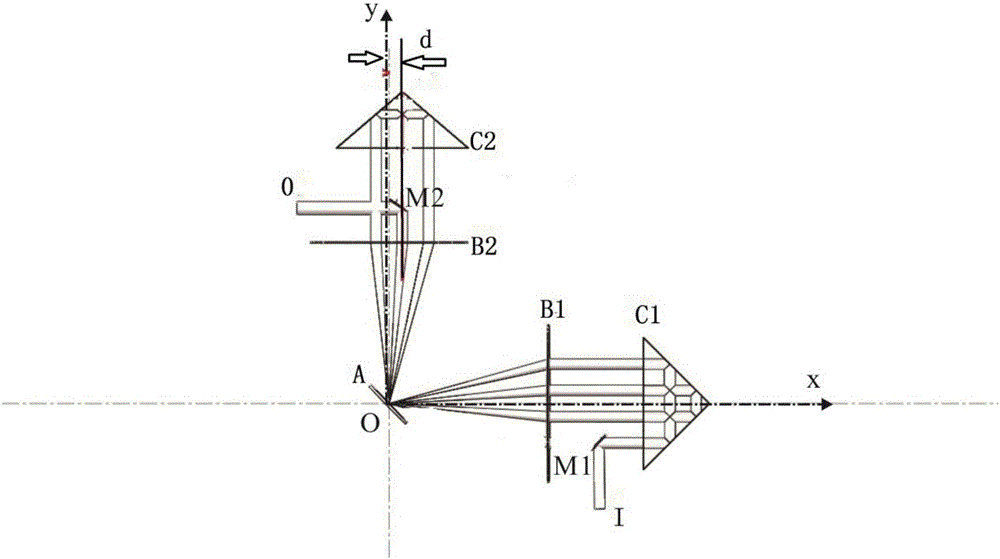
[0064] image 3 It is a schematic plan view of the structure of the disk laser amplifier of embodiment 1, including disk crystal A, lens B1, lens B2, right-angle prism C1, and right-angle prism C2. The diameter of all lenses is D, the focal length is f, and the optical axis is Located on the horizontal plane xOy, the reflective or transmissive surfaces of all devices are perpendicular to the horizontal direction; the front of the disc crystal A has an anti-reflection film, and the back has a total reflection film; its back is oppositely provided with a parabolic reflector for semiconductor The pump light output by the laser is reflected to the back of the disc crystal. By selecting the pump module inside the disc crystal or selecting the parameters of the lens, the spot size of the pump light can be made to be the same as that of the seed light. When the active particles inside the disc crystal absorb the pump light, they transition from the ground state to the excited state,...
Embodiment 2
[0069] Figure 6 It is a top view plan view of the structure of the disc laser amplifier in embodiment 2. The structure of all devices is the same as in embodiment 1. The difference is that we replace it with a right-angle mirror at the position of the original output unit M2, and the intersection line of the two reflection planes is parallel to the x-axis. , the reflector translates the light for a distance S in the z direction and reverses the light propagation in reverse and enters the lens C2 again to continue to oscillate and amplify. And according to the theory of light reflection, it is easy to know that after passing through the right-angle mirror R0, if the vertical distance (z direction) of the light spot on the lens B2 increases by S, then after the reflection of the disc, the light spot on the lens B1 is in the z direction Reduced S.
[0070] Figure 7 The schematic diagram of the structure space of the disk laser amplifier shown in Example 2, we can get the spec...
Embodiment 3
[0074] Figure 9 and Figure 10 The schematic diagram of the structure space of the disc laser amplifier of the shown embodiment 3, the change of the embodiment 3 compared with the embodiment 1 is mainly that the symmetry axis of the main section of the rectangular prism C2 coincides with the optical axis (y axis) of the lens B2, that is, the horizontal distance d is 0, but is rotated by a certain angle θ around the y-axis on this basis. In this embodiment, we take it as 90 degrees for simplicity of analysis. (For the convenience of drawing only in Figure 9 The mark that the rectangular prism C2 is rotated by 90 degrees is marked, and the following figures are omitted)
[0075] Similarly, the propagation route of the seed light is: I→C1→B1→A→B2→C2→B2→A→B1→C1→B1→A→B2→C2→O, a total of 3 times through the disc crystal, and the number of times of amplification for 6.
[0076] Figure 11 The sequence paths of the seed light spots hitting the lenses B1, B2, and rectangular pri...
PUM
 Abstract
Description
Claims
Application Information