CT bulb tube current control method, control system and CT imaging method

A technology of tube current and control method, applied in CT tube current control method, control system, and CT imaging field, can solve the problems of high price, shortened CT tube filament life, easy damage of CT machine, etc., and achieves good real-time performance. , powerful computing speed, flexible programming effect

Inactive Publication Date: 2017-05-24
SHANGHAI UNITED IMAGING HEALTHCARE
View PDF3 Cites 8 Cited by
  • Summary
  • Abstract
  • Description
  • Claims
  • Application Information

AI Technical Summary

Problems solved by technology

[0005] During the entire imaging process, the X-ray tube is one of the most important components of the CT system, because it provides the necessary X-rays for CT scans, it is expensive, and it is also the most easily damaged part of the CT machine
In the process of medical diagnosis by CT machine, the method of increasing the X-ray dose is used at the beginning to obtain more and clearer image information, but this method also shortens the life of the CT tube filament to some extent

Method used


Image

  • CT bulb tube current control method, control system and CT imaging method
  • CT bulb tube current control method, control system and CT imaging method
  • CT bulb tube current control method, control system and CT imaging method

Examples


Embodiment Construction

[0035] In order to make the above objects, features and advantages of the present invention more obvious and comprehensible, specific implementations of the present invention will be described in detail below in conjunction with the accompanying drawings and embodiments.

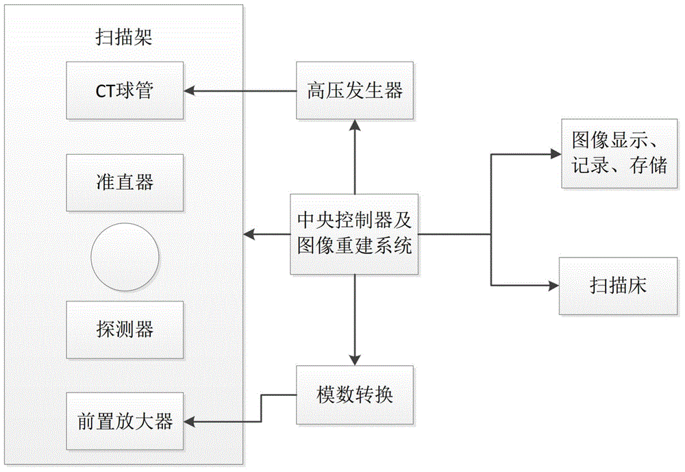
[0036] The medical exposure received by many examinees and patients has become the largest and ever-increasing source of artificial ionizing radiation exposure among various ionizing radiation exposures. In recent years, CT has become more and more widely used in radiological diagnosis, and the number of equipment and the number of people receiving CT examinations have increased year by year. In order to minimize the radiation dose received by the subject, it is necessary to optimize the conditions of CT scanning and strictly control the exposure of tube X-rays. Such as figure 1 It is a schematic diagram of the composition and structure of the CT scanning machine used in the present invention, mainly includ...


PUM


Abstract

The invention discloses a CT bulb tube current control method. The method comprises the following steps that a central controller is provided, wherein the central controller obtains bulb tube mA value data with timestamp information according to the attenuation value of a scanned part; a processing module is provided, the processing module receives the mA value data output by the central controller and screens out effective mA value data within the setting time threshold value range; two adjacent effective mA value data are subjected to interpolation processing and caching, a high-voltage generator is provided, and the high-voltage generator controls CT bulb tube X ray dosage to be exposed. According to the CT bulb tube current control method, interpolation processing is conducted on the bulb tube mA value data which is issued by the central controller and has longer time intervals, the bulb tube mA value data having more time subdivisions in the scanning process is obtained, and high-precision real-time control over a CT bulb tube is achieved. Meanwhile, the invention further provides a CT bulb tube current control system and a CT imaging method.

Description

[0001] 【Technical field】 [0002] The invention relates to the technical field of computer tomography, in particular to a CT tube current control method, a control system and a CT imaging method. [0003] 【Background technique】 [0004] Since the advent of Computed Tomography (CT) equipment, the imaging technology has developed extremely rapidly and the equipment has been continuously updated. In medicine, it is used to diagnose spinal and head injuries, intracranial tumors, blood clots in the brain, soft tissue injuries, gastrointestinal diseases, malignant lesions of the waist and pelvis, etc. The basic process of its imaging includes: X-rays are emitted from the focal position of the CT tube and pass through the human body to reach the detector; the detector receives the X-rays passing through this layer and converts them into energy intensity signals; the data acquisition and processing system collects the energy intensity signals , and combined with a certain algorithm to...

Claims


Application Information

Patent Timeline
Patent Type & Authority Applications(China)
IPC IPC(8): A61B6/03G06F17/50G06T1/00G06T11/00
Inventor 孔德新
Owner SHANGHAI UNITED IMAGING HEALTHCARE
Why Eureka
Try Eureka