
Surgery endoscope device with feedable, retractable and orientation-rotatable laser emission window

An endoscope, advancing and retracting knife technology, applied in the direction of the catheter, etc., can solve the problems of the laser knife edge can not be rotated or can be rotated but must be rotated directly by hand, inconvenient operation, poor control, etc., to improve the success rate of surgery and the learning curve. The effect of reducing, reducing requirements

Pending Publication Date: 2017-05-24
爱科凯能科技(北京)股份有限公司
View PDF10 Cites 3 Cited by
  • Summary
  • Abstract
  • Description
  • Claims
  • Application Information

AI Technical Summary

Problems solved by technology

[0006] In order to overcome the above-mentioned traditional endoscope (laser cystoscope or resectoscope) either cannot be used for clinical treatment of soft tissue with side-firing laser fiber or side-firing laser sheath, or the direction of the laser incision cannot be rotated or can be rotated but must be rotated directly by hand, or At the same time, the disadvantages of inconvenient operation and poor maneuverability caused by rotating the working hand piece, the present invention aims at the corresponding structure of the side-firing laser fiber, especially the side-firing laser sheath, and clinical surgical treatment such as prostate, bladder tumor, etc., invented a laser incision The position of the surgical endoscope can be advanced and retreated and the orientation can be rotated. By operating the axial movement control part of the working hand piece, the position of the laser knife edge can be advanced and retracted. Handpiece for precise and convenient rotation of the laser edge orientation

Method used


Image

  • Surgery endoscope device with feedable, retractable and orientation-rotatable laser emission window
  • Surgery endoscope device with feedable, retractable and orientation-rotatable laser emission window
  • Surgery endoscope device with feedable, retractable and orientation-rotatable laser emission window

Examples


Embodiment Construction

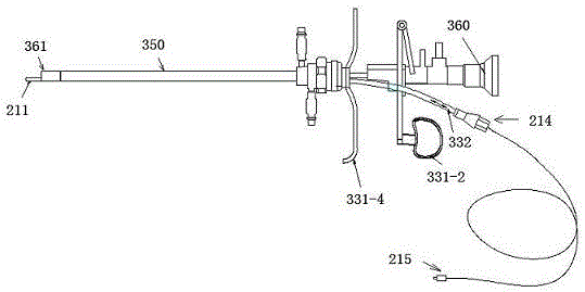
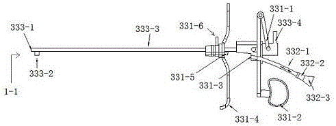
[0019] For side-firing laser sheath 200 as Figure 8 As shown, its axis 212, its laser edge 211 emits laser, and the angle between the direction 207 of emitting laser and the axis 212 is generally in the range of 30-90°. For lesions such as prostate gland and bladder tumor, the emitted laser is exactly vertical Acting on the tissue, it has a better effect on soft tissue than the direct laser fiber that is parallel to the focus of the laser. The laser incision is located at the head end 210 of the laser sheath 200, and the head end of the laser sheath is usually a hard material structure such as a metal head end. In order to facilitate operation and fixation, the laser sheath 200 usually also has a handle 214, and the part between the handle 214 and the head end 210 is usually a working part, and its length becomes the working length. For laser fiber type, the working part 213 is usually a flexible cable structure. For laser sheaths, the working part is usually a cylindrical s...


PUM


Abstract

The invention relates to a surgery endoscope device with a feedable, retractable and orientation-rotatable laser emission window. The surgery endoscope device is characterized in that a laser emission window feeding and retracting axial motion control part and an orientation rotation motion control part are used to precisely and conveniently control the axial position and orientation of the laser emission window of especially a side-emission laser sheath or traditional manual and direct operation of the laser sheath (including the side-emission optical fibers) or an operation manner rotating an endoscope is replaced, a visual surgery field which can be monitored in real time is obtained, laser energy is allowed to safely and efficient act on the lesion of a human body, and clinical treatment of part of lesions such as prostate hyperplasia and bladder tumor of the human body can be completed. By the device, a surgeon can simply and conveniently operate a laser scalpel, and a learning curve becomes easy.

Description

technical field [0001] The invention belongs to an endoscope device whose laser edge position can advance and retreat and the edge orientation can be rotated. When it is used for laser treatment of soft tissue diseases of human body, the edge position and orientation of side-firing laser sheath or side-firing optical fiber can be precisely and conveniently controlled. Carry out precise and efficient treatment of human soft tissue lesions. Background technique [0002] Lasers have been widely used in the minimally invasive treatment of human diseases, and there are two types of direct-firing laser fibers and side-firing laser fibers used in clinical practice. Direct laser fiber is a kind of laser energy transmitted to the lesion through the laser fiber. The laser energy is emitted from the far end of the laser fiber, that is, the laser incision or the laser emission window (hereinafter collectively referred to as the laser incision), and acts on the human soft tissue lesion. ...

Claims


Application Information

Patent Timeline
IPC IPC(8): A61B18/24
CPCA61B18/24
Inventor 董强唐汇龙孔垂泽朱延军熊振宏申路加
Owner 爱科凯能科技(北京)股份有限公司
Learn More