Tool clamp for transverse automatic welding of large spherical shell structure and assembling method

A spherical shell structure and automatic welding technology, applied in the direction of welding equipment, manufacturing tools, auxiliary welding equipment, etc., can solve the problem of inability to realize positioning, measurement, adjustment and assembly functions, inability to realize external indirect connection and fixation of spherical shell structure, spherical shell The structure has no problems such as positioning, adjustment and measurement position, which is beneficial to deformation control, improving process space margin, and improving processing margin.

Active Publication Date: 2017-05-24
AVIC BEIJING AERONAUTICAL MFG TECH RES INST
View PDF9 Cites 7 Cited by
  • Summary
  • Abstract
  • Description
  • Claims
  • Application Information

AI Technical Summary

Problems solved by technology

[0003] Due to the large size of the spherical shell, in the prior art, the structure of the spherical shell parts is generally subjected to automatic argon arc welding and electron beam welding in the semi-finishing state or after finishing. Except for the welding butt joint surface, the spherical shell structure itself has no positioning, adjustment and adjustment. Measuring position, therefore, welding jigs and assembly methods are difficult and inconvenient for assembly adjustments
In addition, the height of the parts of the welding fixture in the prior art is relatively high, so the space margin of the electron beam welding process is small, and the functions of positioning, measurement, adjustment and assembly cannot be realized. The rigidity of the spherical shell window is not ideal, and the spherical shell structure cannot be realized. The external indirect connection is fixed, the accuracy of the welding position and the welding gap are not ideal, which will affect the weld formation, welding quality and other issues

Method used


Image

  • Tool clamp for transverse automatic welding of large spherical shell structure and assembling method
  • Tool clamp for transverse automatic welding of large spherical shell structure and assembling method
  • Tool clamp for transverse automatic welding of large spherical shell structure and assembling method

Examples


Embodiment 1

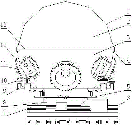
[0031] Such as figure 1 As shown, a tooling fixture for horizontal automatic welding of a large spherical shell structure includes a fixture body, the fixture body includes a spherical shell 1 and a welding fixture 6, the spherical shell 1 includes an upper hemispherical shell 2 and a lower hemispherical shell 3, and the upper hemispherical shell 2 and the lower hemispherical shell 3 is provided with an equatorial weld 13, the equatorial weld 13 is provided with a boss 4, the outer surface of the lower hemispherical shell 3 is provided with a window 12, and the end of the window 12 located at the outer side of the spherical shell 1 is provided with The outer pressure plate 11 and the end of the window 12 located inside the spherical shell 1 are provided with an inner pressure plate, the outer pressure plate 11 and the inner pressure plate are connected with the window 12 by bolts, and the welding fixture 6 includes a lifting fixture 9 connected with the lower hemispherical shel...

Embodiment 2

[0034] Such as figure 1As shown, a tooling fixture for horizontal automatic welding of a large spherical shell structure includes a fixture body, the fixture body includes a spherical shell 1 and a welding fixture 6, the spherical shell 1 includes an upper hemispherical shell 2 and a lower hemispherical shell 3, and the upper hemispherical shell 2 and the lower hemispherical shell 3 are provided with an equatorial weld 13, and a boss 4 is arranged on the equatorial weld 13. The boss 4 not only ensures the supporting effect on the welding pool, but also increases the welding processing allowance and improves the size. The processing margin ensures the finished product rate of the parts, and provides a reference position for the assembly of the parts. The outer surface of the lower hemispherical shell 3 is provided with a window 12, and the end of the window 12 located on the outer side of the spherical shell 1 is provided with an outer pressure plate. 11. The end of the window ...


PUM

PropertyMeasurementUnit
thicknessaaaaaaaaaa

Abstract

The invention discloses a tool clamp for transverse automatic welding of a large spherical shell structure and an assembling method. The tool clamp is characterized by comprising a clamp body; the clamp body comprises a spherical shell and a welding clamp; the spherical shell comprises an upper half spherical shell body and a lower half spherical shell body; an equator welding joint is arranged between the upper half spherical shell body and the lower half spherical shell body; a boss is arranged on the equator welding joint; and the welding clamp comprises a lifting clamp connected with the lower half spherical shell body. The assembling method includes the steps that a platform trolley is loaded to a vacuum chamber guide rail; the lifting clamp is assembled to a rotary table; the lower half spherical shell body is loaded to a supporting cylinder bevel structure of the lifting clamp; a bolt between an L-shaped joint plate and the lifting clamp is synchronously and symmetrically locked; the upper half spherical shell body is assembled to the lower half spherical shell body; the welding position on the boss between the upper half spherical shell body and the lower half spherical shell body is subjected to spot welding through argon arc welding after assembling is completed; and then the welding position in the spherical shell is subjected to spot welding through argon arc welding, and assembling of the upper half spherical shell body and the lower half spherical shell body is completed. By the adoption of the technical scheme, the assembling requirements for welding position precision, welding gaps, welding order differences and the like are met.

Description

technical field [0001] The invention relates to the technical field of a tooling fixture and an assembly adjustment method, in particular to a tooling fixture and an assembling method for horizontal automatic welding of a large spherical shell structure. Background technique [0002] In many cases of engineering practice, it is necessary to carry out integrated welding for the equator of pressure vessel parts such as large spherical shells. When the welding thickness is 30-150 mm and the equatorial weld length reaches 1-7 meters, automatic argon arc welding is usually used , electron beam welding and other methods for splicing. For example, the spherical shell structure of the manned cabin of the manned deep submersible has an inner diameter of 2.1 meters and a thickness of 50-60 mm. For large-size and large-thickness spherical shell structures, in order to obtain better welding quality, the fixture design and structural positioning and assembly of spherical shell parts bef...

Claims


Application Information

Patent Timeline
Patent Type & Authority Applications(China)
IPC IPC(8): B23K37/04B23K37/047B23K101/12
CPCB23K37/0417B23K37/047B23K2101/12
Inventor 付鹏飞毛智勇王西昌唐振云李凯左从进张田崔向中
Owner AVIC BEIJING AERONAUTICAL MFG TECH RES INST
Why Eureka
Try Eureka