

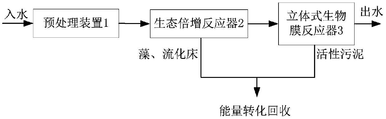
Biological and ecological multiplication reaction system
A reaction system and ecological technology, applied in the direction of water pollutants, water/sewage multi-stage treatment, electrodialysis, etc., can solve the problems of low efficiency of nitrogen and phosphorus removal process, large and small occupied area, and achieve The effect of saving chemical dosage, saving floor area and low operating cost
- Summary
- Abstract
- Description
- Claims
- Application Information
AI Technical Summary
Problems solved by technology
Method used
Image

Examples
Embodiment 1
[0063] The sheet metal electrode assembly 314 includes two electrode plates insulated from each other. The electrode plate is a sheet metal part directly cut or stamped on a thin metal plate, including a plurality of electrodes arranged in a flat shape and one or more lines connecting all electrodes at the same time. The two electrode plates are stacked alternately, so that the electrode of one electrode plate is placed in the space between two adjacent electrodes of the other electrode plate, and the two electrode plates are connected to different AC power sources through the power adapter 320 provided on the flat frame 316. The output terminal forms an electrode group, which generates a non-uniform electric field around it. The two electrode plates can be both insulated, or one can be insulated and the other can be a bare electrode; when one electrode plate is a bare electrode, the electrode plate should be made of corrosion-resistant materials, or undergo corrosion-resistant...
Embodiment 2
[0068] Such as Figure 10 As shown, the difference from Embodiment 1 is that the two electrode plates are grid-shaped electrode plates 326, which are composed of a plurality of electrodes 327 arranged in parallel and two edge lines 328 connecting the two ends of the electrodes. Two grid-shaped electrode plates are stacked at intervals to form an electrode group. An insulating sheet is used between the side lines 328 of the two grid-shaped electrode plates 326 to stack them at intervals. When two grid-shaped electrode plates 326 are overlapped to form a sheet metal DEP electrode structure, the insulating sheet is arranged between the side lines 328 of the two grid-shaped electrode plates 326, which can prevent the side lines 328 of the grid-shaped electrode plates 326 from touching , because the two ends of the electrode 327 are connected together by the side line 328, so the position of the electrode is relatively fixed during installation, and no later adjustment is required...
Embodiment 3
[0070] Such as Figure 11 As shown, the difference from Embodiment 2 is that the two electrode plates are three-dimensional grid-shaped electrode plates 329, and the three-dimensional grid-shaped electrode plates 329 are composed of a plurality of electrodes 330 arranged in parallel and two side lines 331 connecting the two ends of the electrodes. After the two ends of the electrode 330 are bent toward the same side, they are connected to two side lines respectively. A preferred method is: after bending both ends of the electrode 330 in a direction perpendicular to the electrode, then bend 90° in a direction parallel to the electrode 330 to form a ladder shape, so that the middle of the electrode 330 protrudes relative to the two ends. Such as Figure 12 , Figure 13 As shown, the edge parts of the two three-dimensional grid-shaped electrode plates 329 are stacked at intervals, and the electrodes 330 of the two three-dimensional grid-shaped electrode plates 329 are stacked a...
PUM
| Property | Measurement | Unit |
|---|---|---|
| diameter | aaaaa | aaaaa |
Abstract
Description
Claims
Application Information