
Electrochemical element separator and electrochemical element obtained using same

A technology for electrochemical components and chemical components, applied in electrical components, electrochemical generators, electrolytic capacitors, etc., can solve problems such as easy occurrence of internal short circuit, loss of isolation between positive and negative electrodes, easy generation of pinholes, etc., and achieve easy sealing , It is not easy to produce defects, and the effect of suppressing pinholes

Active Publication Date: 2017-05-24
MITSUBISHI PAPER MILLS LTD
View PDF10 Cites 2 Cited by
  • Summary
  • Abstract
  • Description
  • Claims
  • Application Information

AI Technical Summary

Problems solved by technology

However, when such a resin porous film is used as a separator for a lithium ion secondary battery, there is a problem that melting and shrinkage occur when the battery generates abnormal heat, and the function of separating the positive and negative electrodes is lost, resulting in significant damage. internal short circuit
However, in the separators for capacitors described in Patent Documents 5 to 9, when the thickness is reduced to reduce the internal resistance, there is a problem that pinholes are likely to occur and internal short circuits are likely to occur.

Method used


Image

  • Electrochemical element separator and electrochemical element obtained using same
  • Electrochemical element separator and electrochemical element obtained using same

Examples


Embodiment 1-1

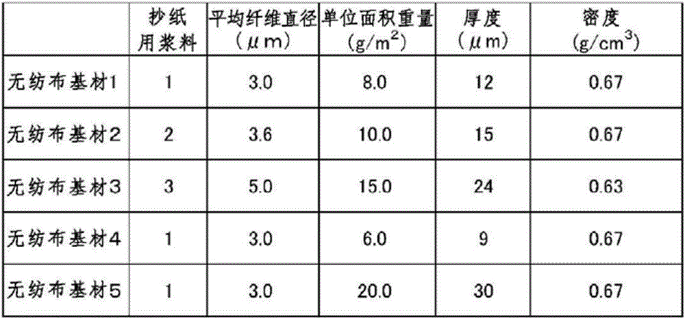
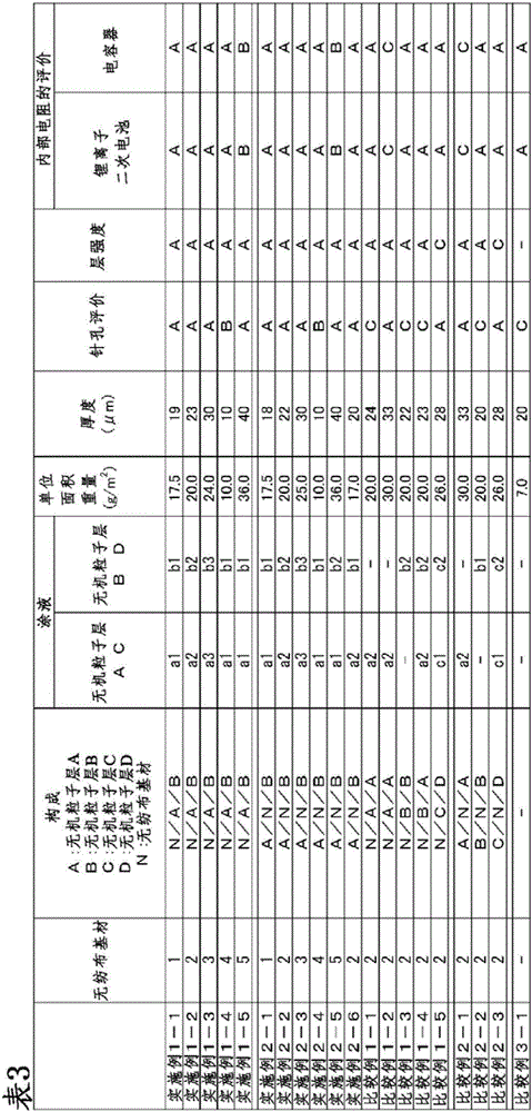
[0109] On the non-woven fabric substrate 1, use a reverse kiss (kiss reverse) type gravure coater to make the coating amount (dry) 7.0g / m 2 After applying the coating liquid a1 by the method and drying it, use a reverse kiss type gravure coater on the same coating surface so that the coating amount (dry) reaches 2.5g / m 2 The coating solution b1 was applied and dried in the same way as above to obtain a separator for an electrochemical element.

Embodiment 1-2

[0111] On the non-woven fabric substrate 2, use a reverse kiss type gravure coater to make the coating amount (dry) 5.0g / m 2 After applying the coating liquid a2 in the same way and drying it, use a reverse kiss type gravure coater on the same coating surface to make the coating amount (dry) 5.0g / m 2 The coating solution b2 was applied and dried in the same way as above to obtain a separator for an electrochemical element.

Embodiment 1-3

[0113] On the non-woven fabric substrate 3, use a reverse kiss type gravure coater to make the coating amount (dry) 3.0g / m 2 After applying the coating liquid a3 by the method and drying it, use a reverse kiss type gravure coater on the same coating surface so that the coating amount (dry) reaches 6.0g / m 2 The coating liquid b3 was applied and dried in the manner described above to obtain a separator for electrochemical elements.


PUM

PropertyMeasurementUnit
diameteraaaaaaaaaa
particle sizeaaaaaaaaaa

Abstract

The purpose of the present invention is to provide: an electrochemical element separator that has excellent manufacturing stability, is without pinholes and has low internal resistance; and an electrochemical element that is obtained using the same. Provided is an electrochemical element separator comprising: a nonwoven substrate; and an inorganic particle layer that contains inorganic particles. The electrochemical element separator is characterized: in that a main constituent of the nonwoven substrate is synthetic resin fibers with an average fiber diameter of 1 to 20 [mu]m; in that the inorganic particle layer includes an inorganic particle layer A that contains magnesium hydroxide with an average particle diameter of 2.0 to 4.0 [mu]m, and an inorganic particle layer B that contains magnesium hydroxide with an average particle diameter of at least 0.5 [mu]m and less than 2.0 [mu]m; and in that the inorganic particle layer A and the inorganic particle layer B are stacked in this order on one surface of the nonwoven substrate; or in that the inorganic particle layer A is provided on one surface of the nonwoven substrate and the inorganic particle layer B is provided on the other surface thereof. The electrochemical element is obtained using the electrochemical element separator.

Description

technical field [0001] The present invention relates to a separator for electrochemical elements and an electrochemical element using the same. Background technique [0002] The separator for the electrochemical element is built in the electrochemical element. The separator for electrochemical elements plays a role in preventing direct contact between the positive electrode and the negative electrode in the electrochemical element. That is, the separator for the electrochemical element isolates the positive electrode and the negative electrode without internal short circuit. In order to reduce the internal resistance of the electrochemical element, it is necessary to form pores capable of effectively permeating ions of the electrolyte in the separator for an electrochemical element. Therefore, the separator for electrochemical elements needs to be porous. [0003] As a lithium ion secondary battery separator used as one type of electrochemical element, resin porous membra...

Claims


Application Information

Patent Timeline
Patent Type & Authority Applications(China)
IPC IPC(8): H01M2/16H01M50/414H01M50/431H01M50/451H01M50/454H01M50/457H01M50/489
CPCH01G9/02H01G11/52Y02E60/10H01M50/44H01M50/431H01M50/446H01M50/489H01M50/454H01M50/457H01M50/451H01M50/414Y02E60/13H01M10/0525H01M2220/20
Inventor 佐藤友洋鬼头昌利
Owner MITSUBISHI PAPER MILLS LTD
Learn More