Catheter with both balloon dilatation function and radiofrequency ablation function and ablation method thereof
A radiofrequency ablation and catheter technology, used in balloon catheters, catheters, dilators, etc., can solve the problems of different blood vessel diameters, inability to fully adhere to the wall, and inability to achieve therapeutic effects, achieving obvious effects, reducing restenosis, maintaining long-term smooth effect
- Summary
- Abstract
- Description
- Claims
- Application Information
AI Technical Summary
Problems solved by technology
Method used
Image

Examples
no. 1 example 〉
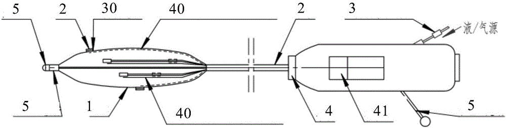
[0043] Such as figure 1 As shown, as the first embodiment of the present invention, a catheter combined with an expandable balloon and a common wall-attached ablation electrode includes a catheter front end 1 , a long tube 2 and a handle 4 .
[0044] The handle 4 is provided with a pressure regulating controller 3 (referred to as pressure controller), a push-pull button 41 and a wire drawing 5 (only the tail end of the wire drawing 5 is shown). The drawing wire 5 passes through the catheter front end 1, the long tube 2 and the handle 4.
[0045] The catheter tip 1 includes a balloon 10 and one or more electrodes 20 attached to the periphery of the balloon 10 . The catheter tip 1 also includes a plurality of thermocouples 40 . As an optional solution, the catheter front end 1 may also include a plurality of pressure sensors 30 . Setting the pressure sensor can intuitively understand the magnitude of the adhesion force of the electrode 20 . The pressure sensor 30 can be omit...
no. 2 example
[0057] For the sake of brevity and effectiveness of description, only the difference between this embodiment and the first embodiment is described here.
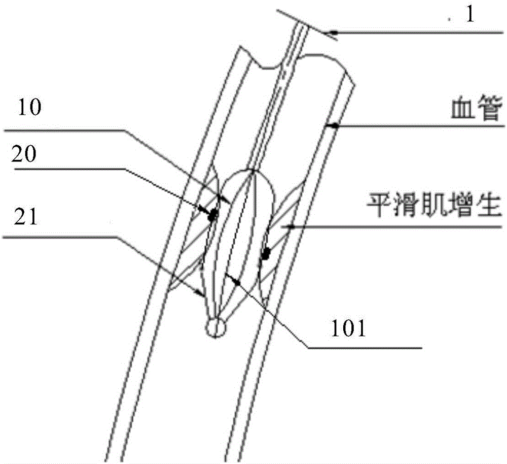
[0058] Such as figure 2 As shown, in this embodiment, the balloon 10 is provided with a fixing bracket 21 outside. One end of the bracket 21 is fixed to the top end of the catheter, and is connected to the head end connector 51 (refer to figure 1 ) on; the other end emerges from the long tube. The fixed stent 21 can be bundled, but cannot be separated from the balloon, including but not limited to a basket-type stent.
[0059] In the figure the support is a basket-type support on which a plurality of electrodes 20 are arranged. After the stent 21 is expanded, the electrode 20 is partially or completely embedded in the tissue, which increases the adhesion force of the electrode and improves the ablation efficiency. The electrode 20 is arranged on the stent wire 211 of the stent 21, such a structure makes the balloon of t...
no. 3 example
[0063] For the sake of brevity and effectiveness of description, only the difference between this embodiment and the first embodiment is described here.
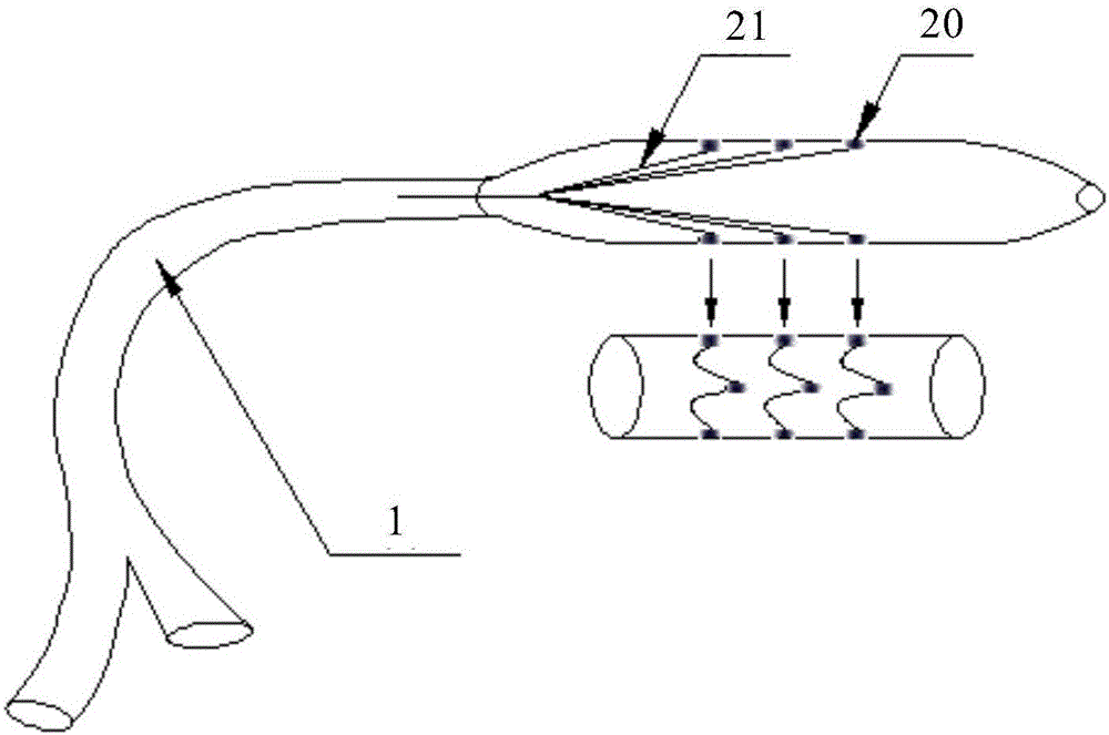
[0064] Unlike the first embodiment and the second embodiment, in combination image 3 ~ Fig. 4, in this embodiment, a detachable stent 21 is provided outside the balloon 10, including a mesh stent, a petal stent or a helical stent (hereinafter collectively referred to as: stent) and the like. After being expanded, the detachable stent 21 can be detached from the balloon 10 and placed in the blood vessel. After the stent 21 is separated from the balloon 10, since the electrode 20 still exists on the balloon 10, after the balloon 10 is moved to a position other than the stent 21, the electrode 20 on the balloon 10 can still expand other blood vessel parts Ablation is now equivalent to a catheter without a stent (first embodiment).
[0065] image 3 Shown is the manner in which the electrodes 20 are arranged on the balloon 1...
PUM
| Property | Measurement | Unit |
|---|---|---|
| Thickness | aaaaa | aaaaa |
| Diameter | aaaaa | aaaaa |
| Diameter | aaaaa | aaaaa |
Abstract
Description
Claims
Application Information
 - R&D
- Intellectual Property
- Life Sciences
- Materials
- Tech Scout
- Unparalleled Data Quality
- Higher Quality Content
- 60% Fewer Hallucinations
Browse by: Latest US Patents, China's latest patents, Technical Efficacy Thesaurus, Application Domain, Technology Topic, Popular Technical Reports.
© 2025 PatSnap. All rights reserved.Legal|Privacy policy|Modern Slavery Act Transparency Statement|Sitemap|About US| Contact US: help@patsnap.com