Waste incineration fume treatment system

A flue gas treatment system and waste incineration technology, applied in the direction of filtration circuit, liquid separation agent, combined device, etc., can solve the unfavorable problems such as widespread promotion and long-term use of waste incineration flue gas treatment technology, poor purification effect, complex structure, etc. , to achieve the effect of ensuring the cooling and purification effect of water washing, strengthening the purification function, and scientific and reasonable design

Inactive Publication Date: 2017-05-31
朱肖州
View PDF8 Cites 2 Cited by
  • Summary
  • Abstract
  • Description
  • Claims
  • Application Information

AI Technical Summary

Problems solved by technology

[0003] However, the current flue gas treatment equipment often has problems such as complex structure, high cost, and poor purification effect, which is not conducive to the widespread promotion and long-term use of waste incineration flue gas treatment technology.

Method used


Image

  • Waste incineration fume treatment system
  • Waste incineration fume treatment system
  • Waste incineration fume treatment system

Examples


Embodiment 1

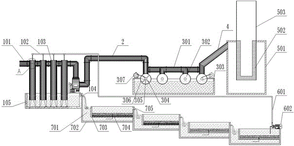
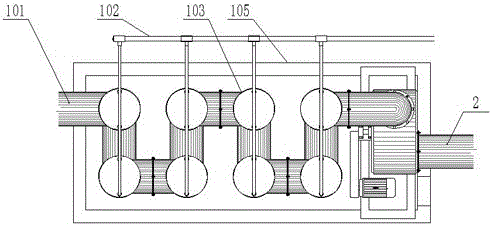
[0041] A waste incineration flue gas treatment system includes a water washing device, a liquefaction device and a filter device; the water washing device is connected to the liquefaction device through a pipeline A2; the liquefaction device is connected to the filter device through a pipeline B4.

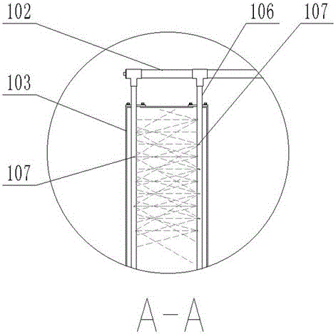
[0042] Described water washing device comprises intake main pipe 101, sedimentation tank 105, water washing tank 103 and spray parts; The top of described water washing tank 103 is connected with intake main pipe 101; 103 are installed in the sedimentation tank 105 according to the staggered front and rear positions; the spray parts include the spray main pipe 102, the spray pipe 106 and the sprayer 107; the water washing tank 103 is provided with a pair of spray Shower pipe 106, spray pipe 106 is vertically installed in the water washing tank 103; described spray pipe 106 is connected in parallel to the spray main pipe 102; The showers 107 on the pair of shower pipes 106 in 103 ar...

Embodiment 2

[0049] This embodiment differs from Embodiment 1 in that:

[0050] The water washing device is provided with 6 groups of water washing tanks 103, and the water washing tanks 103 are arranged in the settling tank 105 in a V-shaped arrangement according to front and rear positions, and the liquefaction device is provided with 4 groups of water turbines. The waste incineration flue gas treatment system also includes a purification device; the purification device includes a multi-stage permeation tank 701, and the permeation tank 701 is arranged in steps; the sedimentation tank 105 is provided with a water outlet A104, and the first-stage permeation tank 701 is connected with the water outlet A104 of the sedimentation tank 105; the osmosis tank 701 includes the pool body 702, the osmosis unit and the water outlet B705; Enclosed; the partition 703 is arranged in the pool body 702; the thickness of the sand-carbon layer 704 is lower than the height of the partition 703; the bottom o...

Embodiment 3

[0052] This embodiment differs from embodiment 2 in that:

[0053] The water washing device is provided with 8 groups of water washing tanks 103, and the water washing tanks 103 are arranged in the settling tank 105 in a staggered front and rear position. The waste incineration flue gas treatment system also includes a circulation system; the circulation system includes a circulation pump 602 and a circulation pipe 601; the circulation pump 602 is installed above the last stage of permeation tank 701; the circulation pump 602 The water inlet pipe is installed above the sand carbon layer 704, and the outlet pipe of the circulation pump 602 is connected with one end of the circulation pipe 601; the other end of the circulation pipe 601 is connected with the spray main pipe 102. The sewage in the sedimentation tank 105 infiltrates through the layers in the permeation tank 701, and the sewage is purified under the action of the sand carbon layer 704, and the purified water can be ...


PUM


Abstract

The invention discloses a waste incineration fume treatment system which comprises a water washing device, a liquefying device and a filtering device, wherein the water washing device is connected with the liquefying device through a pipeline A; the liquefying device is connected with the filtering device through a pipeline B; the water washing device comprises a main air inlet tube, a settling tank, a washing tank and a spraying part; the liquefying device comprises an air pipeline, a driving device, a water turbine and a water storage tank; the filtering device comprises a shell, an activated carbon layer and an air outlet; the main air inlet tube, the pipeline A, the air pipeline and the pipeline B are connected in sequence. Due to the water washing device, the liquefying device and the filtering device, thick fume generated from incineration can be subjected to procedures of water washing purification, high-pressure atomization and filtration discharge in sequence, the structure is simple, the process design is reasonable, and the problem of fume pollution caused by waste incineration can be effectively overcome.

Description

technical field [0001] The invention belongs to the technical field of waste incineration flue gas purification and treatment, and relates to a waste incineration flue gas treatment system. Background technique [0002] With the development of the economy, the amount of domestic waste is also increasing. At present, there are three main methods of domestic waste disposal: sanitary landfill, high-temperature composting and incineration for energy production. Since the two methods of sanitary landfill and high-temperature composting will cause serious environmental pollution problems, incineration to produce energy is the direction of municipal solid waste treatment. However, the flue gas produced by the incineration of domestic waste after high-temperature incineration contains a large amount of harmful components such as dioxins, heavy metals, and HCl, so the flue gas must be treated before being discharged up to the standard. With the vigorous promotion of national energy...

Claims


Application Information

Patent Timeline
Patent Type & Authority Applications(China)
IPC IPC(8): B01D47/06B01D53/00B01D53/18B01D50/00B01D53/04B01D36/04
CPCB01D36/04B01D47/06B01D53/002B01D53/04B01D53/1425B01D53/1456B01D53/1487B01D53/18B01D50/60
Inventor 朱肖州
Owner 朱肖州
Why Eureka
Try Eureka