
Flue gas heat accumulation and denitrification device and denitrification method for industrial furnace

An industrial furnace and heat storage technology, applied in chemical instruments and methods, separation methods, chemical industry, etc., can solve the problems that other methods are in the experimental research stage or pilot test stage, and achieve long service life, low activation temperature, The effect of a compact system

Pending Publication Date: 2017-05-31
SHENWU TECH GRP CO LTD
View PDF0 Cites 1 Cited by
  • Summary
  • Abstract
  • Description
  • Claims
  • Application Information

AI Technical Summary

Problems solved by technology

There are many flue gas denitrification methods, but currently only the selective catalytic reduction method and the selective non-catalytic reduction method have been widely used in industry, and other methods are currently in the experimental research stage or pilot stage

Method used


Image

  • Flue gas heat accumulation and denitrification device and denitrification method for industrial furnace
  • Flue gas heat accumulation and denitrification device and denitrification method for industrial furnace
  • Flue gas heat accumulation and denitrification device and denitrification method for industrial furnace

Examples


Embodiment Construction

[0031] Embodiments of the present invention are described in detail below, examples of which are shown in the drawings, wherein the same or similar reference numerals designate the same or similar elements or elements having the same or similar functions throughout. The embodiments described below by referring to the figures are exemplary and are intended to explain the present invention and should not be construed as limiting the present invention.

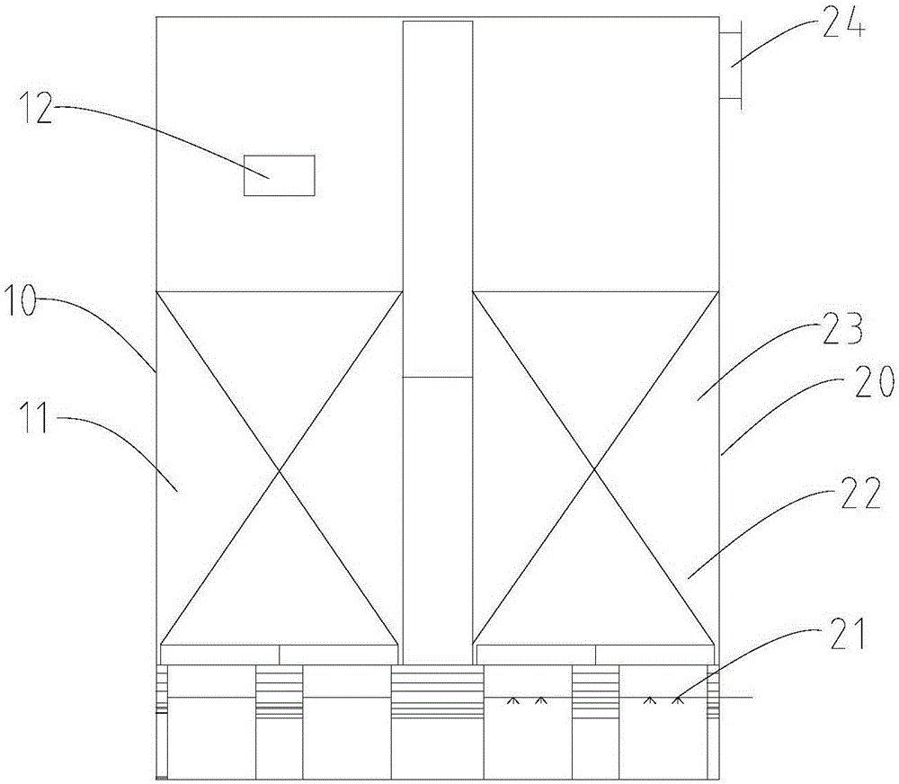
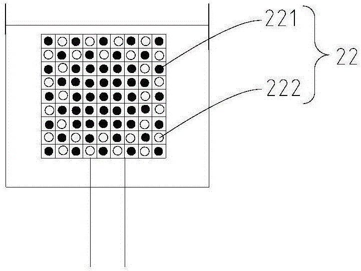
[0032] According to one aspect of the present invention, the present invention proposes an industrial furnace flue gas thermal storage denitrification device, such as figure 1 As shown, the industrial furnace flue gas heat storage and denitrification device of the embodiment of the present invention includes: a first heat storage part 10 and a second heat storage part 20, wherein a high temperature heat storage body 11 is arranged in the first heat storage part 10, so The upper part of the first heat storage part 20 has a first o...


PUM

PropertyMeasurementUnit
diameteraaaaaaaaaa
lengthaaaaaaaaaa
mechanical strengthaaaaaaaaaa

Abstract

The invention discloses a flue gas heat accumulation and denitrification device and a denitrification method for an industrial furnace. The flue gas heat accumulation and denitrification device comprises a first heat accumulation portion and a second heat accumulation portion, wherein a high-temperature heat accumulator is arranged in the heat accumulation portion, and a first opening is formed in the upper portion of the heat accumulation portion; and the second heat accumulation portion is successively divided into an ammonia spraying region and a denitrification and heat accumulation region from bottom to top, a reducer nozzle is arranged in the ammonia spraying region, a denitrification and heat accumulator is arranged in the denitrification and heat accumulation region, a second opening is formed in the upper portion of the second heat accumulation portion, and the bottom end of the second heat accumulation region is communicated with the bottom end of the first heat accumulation portion. The flue gas heat accumulation and denitrification device for the industrial furnace integrates a heat accumulating combustion system and the flue gas denitrification system, so that the denitrification treatment on the flue gas is realized while flue gas waste heat is recovered. The flue gas heat accumulation and denitrification device has double functions of heat accumulation and denitrification.

Description

technical field [0001] The invention belongs to the field of gas denitrification, energy saving and environmental protection. Specifically, the invention relates to an industrial furnace flue gas thermal storage denitrification device and a denitrification method. Background technique [0002] With the rapid development of my country's economy, fossil fuels such as natural gas, oil and coal have been more widely used, making environmental problems increasingly serious, which has caused a series of environmental problems, such as acid rain, ozone layer destruction, greenhouse effect, etc., making us The living environment is becoming more and more severe. my country's coal-based energy structure determines that the emissions of nitrogen oxides and sulfur oxides in our country have always been high. The emission of a large amount of polluting gases has made environmental problems increasingly serious, not only seriously affecting the production and life of our people. , and is ...

Claims


Application Information

Patent Timeline
Patent Type & Authority Applications(China)
IPC IPC(8): B01D53/56B01D53/90B01J23/652C09K5/14F27D17/00
CPCB01D53/8628B01D53/90B01D2258/0283B01J23/6527C09K5/14F27D17/004F27D17/008F27D2017/007Y02P20/10
Inventor 钟贵全杨玉地郭科宏石为华宋敏洁吴道洪
Owner SHENWU TECH GRP CO LTD
Learn More