Waste gas purification device of multifunctional reaction kettle

An exhaust gas purification device and purification device technology, applied in mixers with rotating stirring devices, chemical/physical/physicochemical fixed reactors, gas treatment, etc., can solve the problem of increasing the load of exhaust gas treatment devices and difficult to accurately control materials Liquid weight, affecting the health of employees and other issues, to achieve the effect of changing the uneven mixing, avoiding environmental pollution and resource waste, and accelerating the heat exchange response speed

Inactive Publication Date: 2017-05-31
浙江晨诺高分子材料有限公司
View PDF5 Cites 4 Cited by
  • Summary
  • Abstract
  • Description
  • Claims
  • Application Information

AI Technical Summary

Problems solved by technology

This not only increases the load on the exhaust gas treatment device, but also causes a waste of organic solvents; at the same time, the noise generated by the fan on the reactor and the gas collection pipe is relatively large, and it will directly affect the health of employees in such an environment for a long time
[0005] In addition, the materials put into the reactor are generally weighed on the electronic scale first, and then put into the reactor body through the feed port of the reactor. It is difficult to accurately control the weight of the feed liquid in such a way of manually controlling the charging. The error is relatively large; at the same time, it is necessary to ensure that the feeding port of the feeding material is accurately docked with the feeding port of the reactor. Once the docking is not accurate, the finished product liquid will leak out, resulting in material loss. If the material is toxic or flammable and explosive materials, it is easy to cause accidents, and the existing reactor has single function, low work efficiency and poor stirring effect, which cannot meet the needs of modern chemical production.

Method used


Image

  • Waste gas purification device of multifunctional reaction kettle

Examples


Embodiment 1

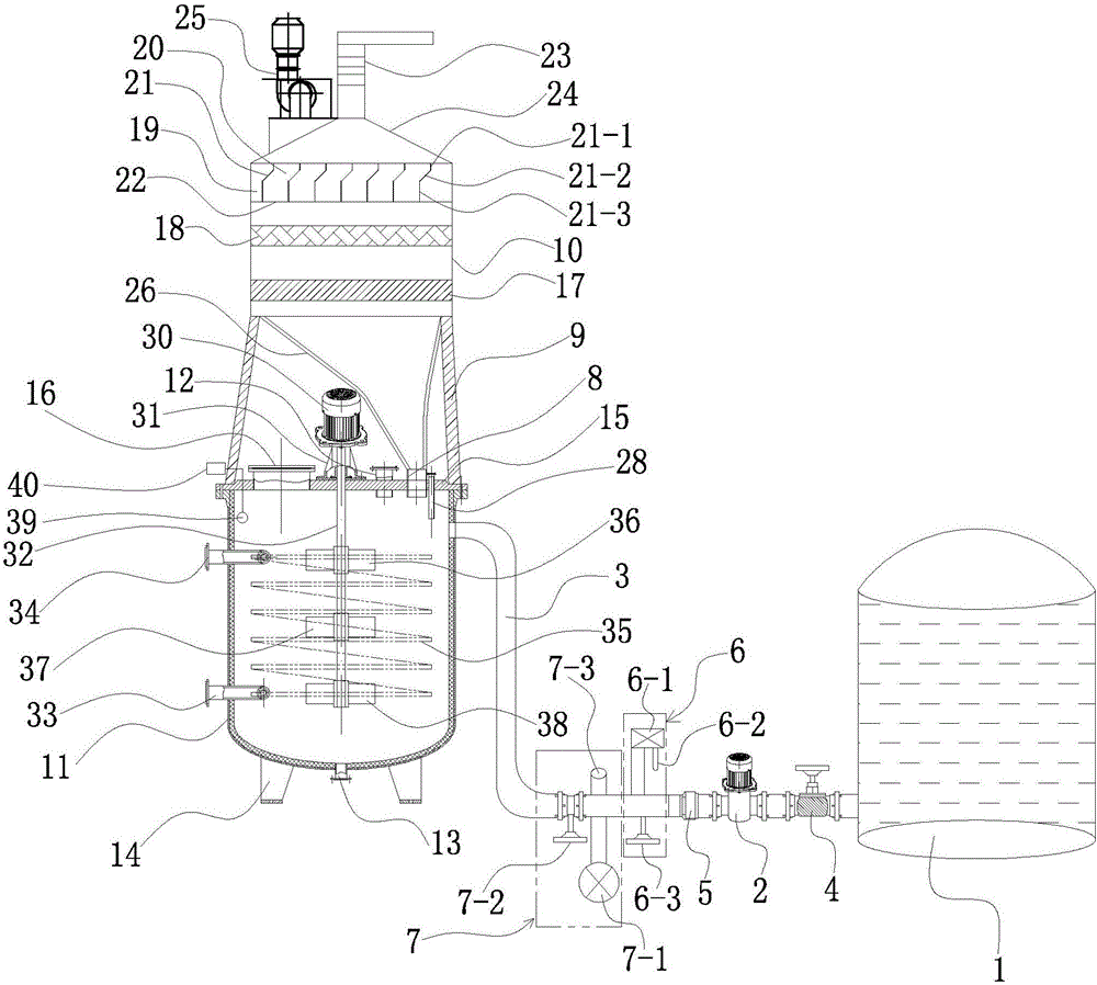
[0027] Embodiment 1: as figure 1As shown, a waste gas purification device of a multifunctional reaction kettle includes a kettle body 11, a waste gas treatment and purification device and a liquid weighing device arranged on the side wall of the kettle body 11; the top of the kettle body 11 is provided with a kettle cover 15, The kettle cover 15 is provided with a manhole 16, a feed port 12, an exhaust hole 8 and a thermometer sleeve 28; the waste gas treatment and purification device is located at the upper end of the kettle body 11 and is fixed by the support seat 9; the bottom of the waste gas treatment and purification device is installed with A horn-shaped connecting pipe 26, the bottom of the connecting pipe 26 is connected to the exhaust hole 8; through the installation of a waste gas treatment and purification device, the connecting pipe 26 is used to process a large amount of high-concentration organic waste gas generated during the reaction to prepare vinyl resin, Ab...


PUM


Abstract

The invention relates to a waste gas purification device of a multifunctional reaction kettle. The waste gas purification device comprises a kettle body, a waste gas treatment and purification device and a liquid weighing device arranged on the side wall of the kettle body, wherein a kettle cover is arranged at the top of the kettle body, and a manhole, a feeding hole, a gas vent and a thermometer sleeve are arranged on the kettle cover; the waste gas treatment and purification device is located at the upper end of the kettle body and fixed through a support seat; a horn type connecting pipe is mounted at the bottom end of the waste gas treatment and purification device, and the bottom of the connecting pipe is connected with the gas vent; with arrangement of a waste gas filtering layer, a waste gas adsorbing layer and a waste gas ventilating layer, a large amount of high-concentration organic waste gas produced in a process of preparing vinyl resin through reaction can be treated and absorbed until reaching emission standard; meanwhile, ventilating wall plates at certain inclined angles are arranged, and noise produced in a fan operating process can be reduced. The device is compact in structure, high in automation degree, and convenient and simple to operate.

Description

technical field [0001] The invention belongs to the technical field of resin processing equipment, and in particular relates to an exhaust gas purification device of a multifunctional reaction kettle. Background technique [0002] Reactors are widely used in petroleum, chemical, rubber, pesticides, dyes, medicines, food, pressure vessels used to complete vulcanization, nitration, hydrogenation, alkylation, polymerization, condensation and other processes, such as reactors, reaction pots, decomposition pots , polymerization kettle, etc.; materials generally include carbon-manganese steel, stainless steel, zirconium, nickel-based (Hastelloy, Monel, Inconel) alloys and other composite materials. The broad understanding of the reaction kettle is a stainless steel container with physical or chemical reactions. The structural design and parameter configuration of the container are carried out according to different process conditions. The design conditions, process, inspection, ma...

Claims


Application Information

Patent Timeline
IPC IPC(8): B01J19/18B01F15/06B01F15/00B01F7/18B01D46/02B01D46/42B01D53/04
CPCB01D46/02B01D46/4236B01D53/04B01J19/002B01J19/18B01D2258/0225B01F27/192B01F27/90B01F35/2117B01F35/2203B01F35/22141B01F35/93B01F2101/2204B01F2035/99
Inventor 王鸿
Owner 浙江晨诺高分子材料有限公司
Why Eureka
Try Eureka