Centrifugal separator for waste spinning fiber

A centrifugal and separator technology, used in centrifuges, solid separation, separation of solids from solids by air flow, etc., can solve the problem of inability to achieve single fiber classification and separation, and achieve low energy consumption and sorting efficiency The effect of high, simple equipment structure

Inactive Publication Date: 2017-05-31
林雁 +2
View PDF3 Cites 3 Cited by
  • Summary
  • Abstract
  • Description
  • Claims
  • Application Information

AI Technical Summary

Problems solved by technology

JWF1053 and FA dust removal machines of Jingwei Textile Machinery, the working principle is dust collection by throwing materials, textile raw materials are thrown from the air duct in the working box, and the material throwing receiving plate is a mesh filter plate, and the negative plate is behind the mesh plate. Compressed air chamber, when the raw materials are dropped, the dust and short fibers in the raw materials will be taken away with the negative pressure air system of the mesh to achieve the purpose of impurity removal and short fiber separation. The working principle of these two typical equipment is the same, only the dust removal function , unable to achieve single fiber length classification and separation

Method used


Image

  • Centrifugal separator for waste spinning fiber
  • Centrifugal separator for waste spinning fiber
  • Centrifugal separator for waste spinning fiber

Examples


Embodiment Construction

[0033] The present invention is described in detail below in conjunction with accompanying drawing and embodiment, and wherein accompanying drawing constitutes a part of this application, but those skilled in the art should know that the following embodiment is not the only limitation that the technical scheme of the present invention is done, Any equivalent transformation or modification made under the spirit of the scheme shall be deemed to belong to the protection scope of the present invention.

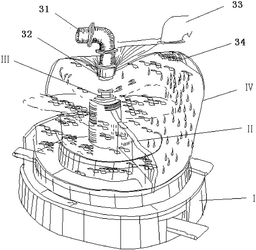
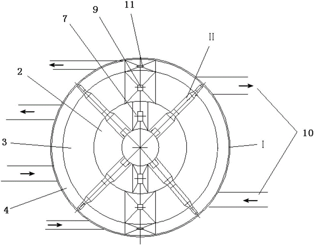
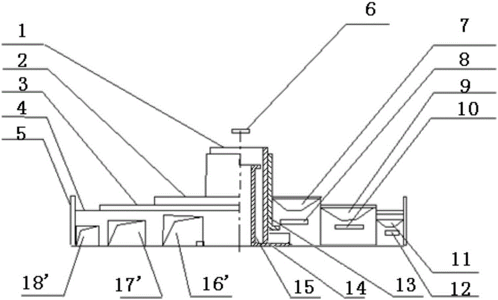
[0034] The machine utilizes the unique centrifugal effect formed by the special structure design, and obtains the classification of mixed recycled fibers, which can realize the separation of four types of fibers, namely: the separation of first-class fibers, second-class fibers, third-class fibers and waste spinning dust.

[0035] pass figure 1 , 2 As shown, the machine mainly includes four groups of parts: main frame I, rotary frame II, impeller assembly III, and hood assembly I...


PUM


Abstract

The invention discloses a centrifugal separator for waste spinning fiber. The centrifugal separator comprises a main machine frame, a rotation machine frame, an impeller assembly and a hood assembly. The main machine frame comprises stepped disc type sorting tables, wherein each stage of sorting table is provided with a discharge port and a conveyor belt. The rotation machine frame comprises rotary rotation machine frame arms. The bottoms of the rotation machine frame arms are connected with platform material collection plates. Materials, scraped and swept by the platform material collection plates, on the stepped disc type sorting tables enter discharge ports. The impeller assembly comprises a sorting main impeller. A gas flow pressure nozzle is arranged at the bottom of the sorting main impeller and blows gas towards the bottom edge of the sorting main impeller. According to the centrifugal separator, the gravity effect of the materials themselves is overcome through the centrifugal effect of the impeller and the blowing effect of the gas flow, and therefore the materials can do the scattering movement in the air; classified falling is achieved through the time during which the materials are scattered in the air; and classified collection of the scattered materials is achieved through the sorting tables and conveyor belts of different heights, and classified separation of the waste spinning fiber is achieved.

Description

technical field [0001] The invention relates to textile fiber processing equipment, in particular to a centrifugal fiber separator. Background technique [0002] In the production of textile raw materials in the early stage of the cotton spinning project, the separation of textile fibers is not urgent. Whether it is cotton, hemp, silk, chemical fiber or recycled fiber, they are all processed and produced for the same material fiber in the production process of pre-spun raw materials. In the opening and carding production of cotton fiber, my country's cotton spinning technology only solves the separation technology of cotton fiber dust and short fiber, seed removal, cotton impurities, etc., and cannot separate and classify fiber quality and physical length. Even in the special technology for foreign fiber separation, it only solves dust removal, metal particle separation, foreign matter and heavy object separation, or foreign color, foreign fiber detection and separation, an...

Claims


Application Information

Patent Timeline
Patent Type & Authority Applications(China)
IPC IPC(8): B04B5/10B04B5/12B04B7/00B04B15/06B04B11/08B07B4/02
CPCB04B5/10B04B5/12B04B7/00B04B11/08B04B15/06B07B4/02
Inventor 林雁张荣高尚友
Owner 林雁
Why Eureka
Try Eureka