Smoke discharge equipment and method for substation antenna soldering

A base station antenna and soldering technology, which is applied to welding equipment, metal processing equipment, auxiliary devices, etc., can solve the problems of decreased cooling effect in the production workshop space, increased air conditioning load, waste of resources, etc., to improve the efficiency and accuracy of the soldering iron, Reduce air-conditioning loss and ensure air quality

Inactive Publication Date: 2017-05-31
东莞市振亮精密科技有限公司
View PDF5 Cites 0 Cited by
  • Summary
  • Abstract
  • Description
  • Claims
  • Application Information

AI Technical Summary

Problems solved by technology

Some welding cable terminal positions are mobile operations, and the soldering will move relatively with the flow of the product. At this time, the mouth of the smoking hood cannot be aligned with the soldering position, and the generated smoke cannot be sucked away in time.
In order to increase the smoking effect, the power of the hood will be increased, and the pipe opening will also be enlarged at the same time. When multiple large-diameter smoking pipes are opened at the same time, the space cooling effect of the production workshop will decrease, and the convection between the smoke that cannot be sucked and the air will be reduced. Increase the load of air conditioning, make the working environment of the workshop worse, and waste resources at the same time

Method used


Image

  • Smoke discharge equipment and method for substation antenna soldering
  • Smoke discharge equipment and method for substation antenna soldering
  • Smoke discharge equipment and method for substation antenna soldering

Examples


Embodiment

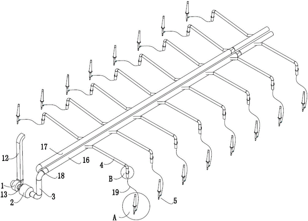
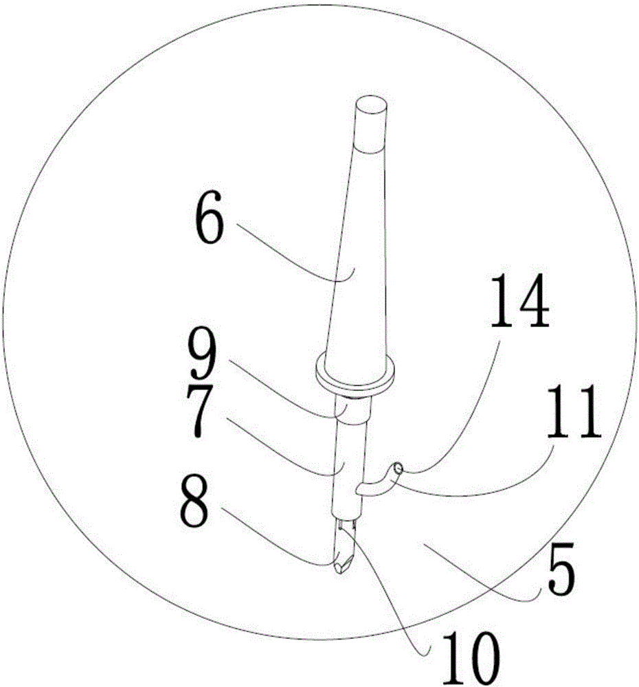
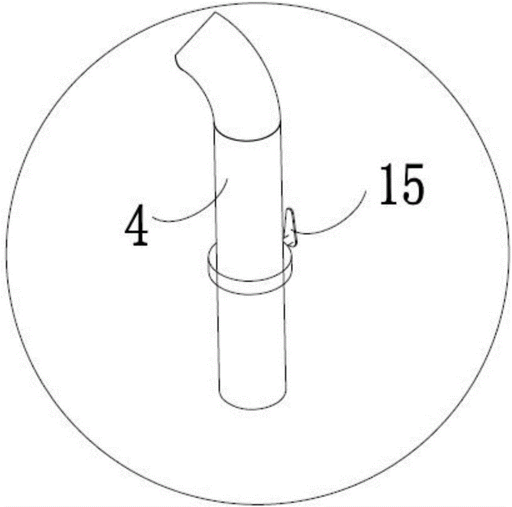
[0026] Example: such as Figure 1 to Figure 3 As shown, the present invention is a base station antenna soldering smoke exhaust equipment, which includes a smoke exhaust machine 1, a filter 2, a smoking main pipe 3 and several branch pipes 4 connected in sequence, and the branch pipes 4 are connected with a soldering iron smoking pipe. The soldering iron smoker 5 includes a soldering iron handle 6, a smoking support 7 and a soldering iron head 8 sequentially connected from top to bottom, the lower end of the soldering iron handle 6 is provided with a fixed joint 9, and the lower end of the fixed joint 9 is connected to the The upper end of the smoking support 7 is connected, and the lower end of the smoking support 7 is connected to the upper end of the soldering iron tip 8. The smoking support 7 is a cylindrical structure, and a number of smoke collectors are arranged on the upper wall of the soldering iron tip 8. A hole 10 is provided in the smoking support 7 corresponding t...


PUM


Abstract

The invention discloses smoke discharge equipment for substation antenna soldering. The smoke discharge equipment comprises a smoke sucking machine, a filter, a smoke sucking main pipeline and a plurality of branch pipelines, wherein the smoke sucking machine, the filter, the smoke sucking main pipeline and the branch pipelines are sequentially connected, a soldering iron smoker sucker is connected to each branch pipeline, each soldering iron smoker sucker comprises a soldering iron handle, a cylindrical smoke sucking support part and a soldering iron head which are sequentially connected, a fixing connector is arranged at the lower end of each soldering iron handle, the lower end of each fixing connector is connected with the upper end of the corresponding smoke sucking support part, the lower end of each smoke sucking support part is connected with the upper end of the corresponding soldering iron head, a plurality of smoke collecting holes are annularly formed in the peripheral wall of each soldering iron head, through holes corresponding to the smoke collecting holes are formed in each smoke sucking support part, each smoke sucking support part is provided with a smoke sucking pipe, the through holes of each smoke sucking support part are communicated with the lower end of the corresponding smoke sucking pipe, and the upper end of each smoke sucking pipe is connected with the corresponding branch pipeline. The invention further discloses a smoke discharge method. By the smoke discharge equipment and method, smoke generated at the soldering moment can be sucked effectively, the air quality of a workshop is guaranteed, cold air consumption of an indoor air conditioner can be reduced, and energy conservation and consumption reduction are achieved.

Description

technical field [0001] The invention relates to the technical field of welding of communication antenna parts, in particular to a base station antenna soldering smoke exhaust equipment and a smoke exhaust method. Background technique [0002] When soldering components, the tin wire volatilizes smoke after being exposed to high temperature. The existing soldering smoke exhaust methods are basically fixed on the assembly line body or welding unit table, and use large pipes to absorb the smoke. Some soldering cable terminal positions are mobile operations, and the soldering will move relatively with the flow of the product. At this time, the mouth of the smoking hood cannot be aligned with the soldering position, and the generated smoke cannot be sucked away in time. In order to increase the smoking effect, the power of the hood will be increased, and the pipe opening will also be enlarged at the same time. When multiple large-diameter smoking pipes are opened at the same time,...

Claims


Application Information

Patent Timeline
Patent Type & Authority Applications(China)
IPC IPC(8): B23K3/08
CPCB23K3/08B23K2101/36
Inventor 高浩哲曾文友相继超陈洪胜魏艳伟
Owner 东莞市振亮精密科技有限公司
Why Eureka
Try Eureka