Friction stir welding method based on hawk energy and mixed surface nanocrystallization technology

A technology of friction stir welding and nanotechnology, which is applied in welding equipment, non-electric welding equipment, metal processing equipment, etc., can solve the problems that affect the comprehensive performance of welded joints and large surface roughness, and achieve convenient manufacturing and maintenance, simple replacement, The effect of simple and easy process

Inactive Publication Date: 2017-05-31
中国人民解放军火箭军工程大学
View PDF0 Cites 1 Cited by
  • Summary
  • Abstract
  • Description
  • Claims
  • Application Information

AI Technical Summary

Problems solved by technology

[0003] After friction stir welding of metal materials, the weld seam is under the action of high-temperature thermal cycle generated by friction stir, and the strengthening phase is coarsened or melted back, resulting in the heat-mechanically affected zone of the weld seam being the weak link of the welded joint. , tensile strength, corrosion under stress and other aspects need to be improved urgently. At the same time, the surface roughness of the friction stir welded joint is very large, which further affects the comprehensive performance of the welded joint.

Method used


Image

  • Friction stir welding method based on hawk energy and mixed surface nanocrystallization technology
  • Friction stir welding method based on hawk energy and mixed surface nanocrystallization technology
  • Friction stir welding method based on hawk energy and mixed surface nanocrystallization technology

Examples


Embodiment Construction

[0029] The present invention will be further described below in conjunction with the accompanying drawings and embodiments, and the present invention includes but not limited to the following embodiments.

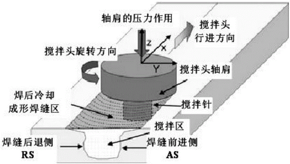
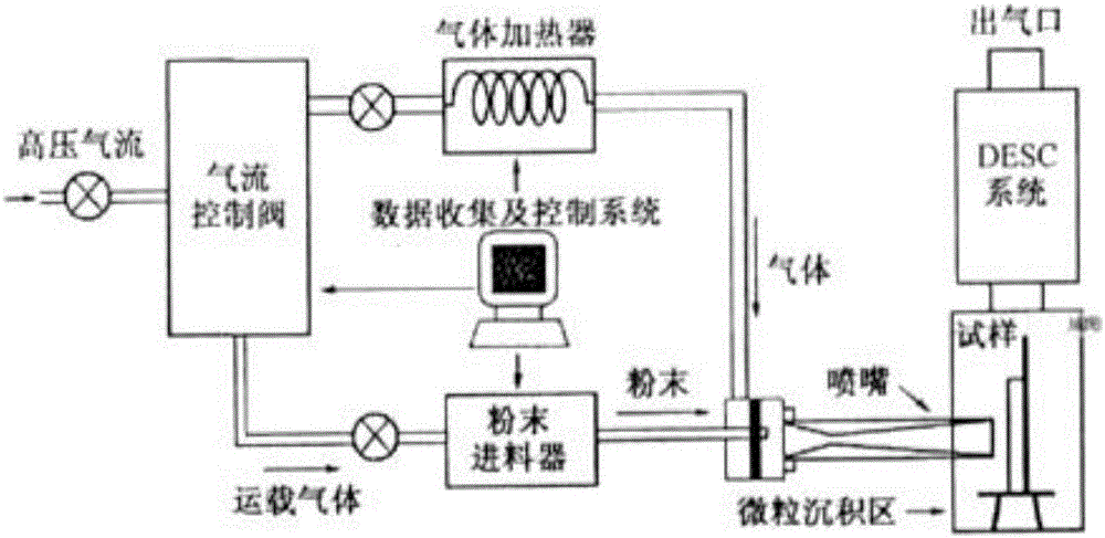
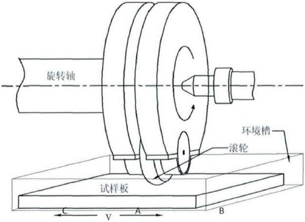
[0030] The invention belongs to the field of friction stir welding of metal materials, and specifically relates to a method for welding the base material to be welded by adopting friction stir welding technology after the surface of the metal base material to be welded is subjected to mixed surface nanometer treatment. The present invention first adopts the supersonic particle bombardment technology, and uses the high-pressure gas generated by the high-pressure gas generating device to carry hard spherical particles to continuously bombard the surface of the metal substrate to be welded at a speed of 340-1200m / s, so that a nano-layer of a certain thickness is formed on the surface , on this basis, the surface of the base material to be welded continues to be processed by sur...


PUM

PropertyMeasurementUnit
thicknessaaaaaaaaaa
sizeaaaaaaaaaa
surface roughnessaaaaaaaaaa

Abstract

The invention provides a friction stir welding method based on a hawk energy and mixed surface nanocrystallization technology. According to the method, firstly, the surface of a base material to be welded is ground and polished; then supersonic particle bombardment surface nanocrystallization treatment is conducted, a nanometer layer with the thickness not lower than 50 micrometers is formed on the surface of the base material to be welded, and the average size of surface nanometer crystals is not greater than 50 nm; surface mechanical rolling is conducted on the surface of the base material to be welded; oil stains on the surface of the base material to be welded are removed with acetone, and then friction stir welding is conducted; trimmings on the upper surface of a joint are shoveled after welding is completed, and a transition zone is polished smoothly; and finally the surface of the welding joint is treated through a hawk energy technology, the surface roughness of the material is reduced to be in the range of 0.01-0.2 micrometers, and the surface microhardness is greater than 300 HV. According to the friction stir welding method, many nanometer layer zones can be formed in the friction stir welding joint, the S-shaped line formation rate caused by the roughness of the welding surface of the base material to be welded is reduced, the surface roughness of the welding joint is improved, and the comprehensive performance of the friction welding joint is improved.

Description

technical field [0001] The invention relates to a friction stir welding method for high-quality welding of metal materials. Background technique [0002] Friction stir welding is a new solid-phase joining technology invented by the British Welding Institute. It can effectively avoid various defects such as pores and cracks caused by traditional fusion welding. It has energy saving and environmental protection, low joining temperature, small residual stress after welding and joint A series of advantages such as high performance can realize high-quality welding of high-strength aluminum alloys (such as 2××× series and 7××× series aluminum alloys) that are traditionally considered unweldable. The schematic diagram of the device is as follows figure 1 . Friction stir welding has received extensive attention since its invention. It is the connection technology with the shortest time span from invention to industrial application in the history of welding technology development in...

Claims


Application Information

Patent Timeline
Patent Type & Authority Applications(China)
IPC IPC(8): B23K20/12B23K20/24
CPCB23K20/1225B23K20/1245B23K20/1255B23K20/24
Inventor 杨建海王敏转张玉祥裴永泉陈家照何祯鑫
Owner 中国人民解放军火箭军工程大学
Why Eureka
Try Eureka