Manufacturing process for prefabricated member

A production process and technology of prefabricated parts, applied in the field of prefabricated parts production technology, can solve the problems of increasing the maintenance cost of the curing kiln, increasing the complexity of the curing kiln, increasing the construction cost, etc., to reduce the occupied area, reduce energy consumption, reduce The effect of maintenance costs

Active Publication Date: 2017-05-31
郑州筑友智造科技有限公司
View PDF7 Cites 3 Cited by
  • Summary
  • Abstract
  • Description
  • Claims
  • Application Information

AI Technical Summary

Problems solved by technology

[0003] In the prior art, in the production line of concrete prefabricated parts, curing is an indispensable production process. In the process of prefabricated parts curing, especially in the process of pre-curing, the poured concrete is usually placed on the transportation line. The molds are stacked on the pallet rack and pushed into the curing kiln for curing through rails, or directly stacked on the support frame of the curing kiln for curing. The combination of these two methods is more complicated and requires strict operation control of the pallet truck. , such as CN105668256A provides a control system for pallet trucks in the curing room of a concrete prefabricated slab production line. The execution unit uses an asynchronous servo motor and an absolute value cable encoder to move the pallet trucks; In the method, the palletizing frame is easily corroded under the conditions of high humidity and high temperature of the curing kiln for a long time. The latter method undoubtedly increases the complexity of the curing kiln, increases its construction cost, and increases the maintenance cost of the curing kiln

Method used


Image

  • Manufacturing process for prefabricated member
  • Manufacturing process for prefabricated member
  • Manufacturing process for prefabricated member

Examples


Embodiment Construction

[0084] The present invention will be described in detail below in conjunction with the accompanying drawings. The description in this part is only exemplary and explanatory, and should not have any limiting effect on the protection scope of the present invention. In addition, those skilled in the art can make corresponding combinations of features in the embodiments in this document and in different embodiments according to the descriptions in this document.

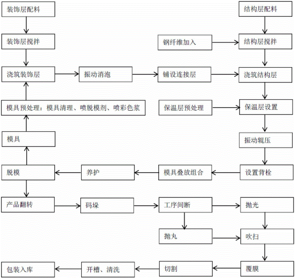
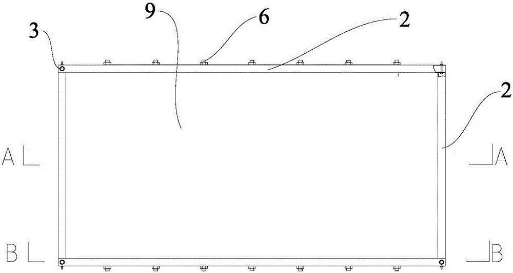
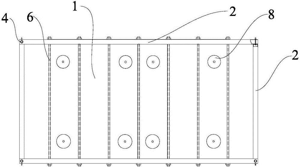
[0085] Embodiments of the present invention are as follows, with reference to figure 1 , Image 6 and Figure 11 , a production process for prefabricated parts, including the following steps: (1) pretreatment of molds: at least including the step of cleaning the molds; (2) batching mixing: weighing each component in the raw material in proportion and then mixing evenly, And the raw material is mixed with water and stirred evenly, and the raw material at least includes cement and fine aggregate; (3) fabric: at least inc...


PUM

PropertyMeasurementUnit
particle size (mesh)aaaaaaaaaa
whitenessaaaaaaaaaa

Abstract

The invention belongs to the field of building element manufacturing, and particularly discloses a manufacturing process for a prefabricated member. The manufacturing process comprises the following procedures that (1) moulds are pretreated; (2) materials are blended; (3) the materials are distributed; (4) the moulds are assembled, specifically, the moulds with the distributed materials are stacked, connecting parts are arranged on the bottom portions and the upper portions of the moulds, and the vertically arranged moulds are fixed through the connecting parts; (5) maintenance is conducted, specifically, the moulds assembled in the procedure (4) are conveyed into a maintenance chamber to be maintained; and (6) demoulding is conducted. In this way, no combined support or other support is needed in the maintenance process, facility maintenance cost is lowered, the production efficiency is improved, and meanwhile, the occupied space area of the whole process production line is greatly reduced. Since the connecting parts are arranged, the moulds are stacked orderly in the assembling process, and meanwhile, a fixing and limiting effect is achieved, so that the forming moulds are prevented from toppling over after being stacked to a certain height or in the transport process.

Description

technical field [0001] The invention belongs to the field of building component production, and in particular relates to a production process of prefabricated parts. Background technique [0002] At present, most of the building construction methods in our country still use the manual method of pouring on site, which has a low level of industrialization and low productivity. With the development of construction industrialization, it has shown huge economic and social benefits, greatly improving resource utilization efficiency and production efficiency. [0003] In the prior art, in the production line of concrete prefabricated parts, curing is an indispensable production process. In the process of prefabricated parts curing, especially in the process of pre-curing, the poured concrete is usually placed on the transportation line. The molds are stacked on the pallet rack and pushed into the curing kiln for curing through rails, or directly stacked on the support frame of the...

Claims


Application Information

Patent Timeline
Patent Type & Authority Applications(China)
IPC IPC(8): B28B1/087B28B1/52B28B13/02B28B7/00B28B11/24B28B13/06B28B23/00C04B28/04C04B28/06B65G61/00
CPCB28B1/087B28B1/522B28B7/0002B28B7/0011B28B7/0023B28B11/245B28B13/02B28B13/065B28B23/00B65G61/00C04B28/04C04B28/06C04B14/06C04B2103/302C04B22/002C04B2103/54C04B2103/65C04B14/068C04B18/08C04B18/146C04B20/0048
Inventor 王术华丑纪能周全
Owner 郑州筑友智造科技有限公司
Why Eureka
Try Eureka