
Thermal resonance fusion engine

A technology of engines and fusion reactors, applied in the field of thermal resonance fusion engines, can solve the problems that electric motors cannot be used alone, high manufacturing, operation and maintenance costs, pollute the atmosphere and the environment, etc., and achieve low operation and maintenance, low total cost, and simple structure Effect

Pending Publication Date: 2017-05-31
董沛 +2
View PDF9 Cites 4 Cited by
  • Summary
  • Abstract
  • Description
  • Claims
  • Application Information

AI Technical Summary

Problems solved by technology

[0017] In order to overcome the existing engines, such as internal combustion engines and external combustion engines, both use fossil fuels, have high fire risks, emit greenhouse gases, pollute the atmosphere and the environment, and have complex overall systems and structures, high manufacturing and operation maintenance costs, and great technical difficulties; Due to the limitation of power supply, it cannot be used alone and is only suitable for working conditions that are fixed or run along a fixed line. The present invention provides a thermal resonance fusion reactor, which can be safe and stable for a long time under ordinary conditions and not too high temperature. operation, while providing green, clean, safe, cheap, and sufficient mechanical power, it can be used as a thermal resonance fusion engine for micro, small, medium, and large engine applications

Method used

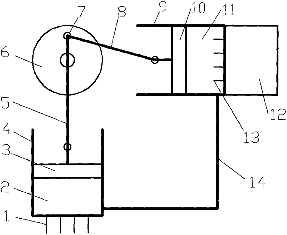
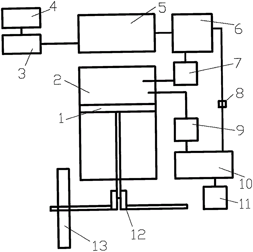

Image

  • Thermal resonance fusion engine
  • Thermal resonance fusion engine
  • Thermal resonance fusion engine

Examples


Embodiment Construction

[0155] When manufacturing a new engine, it must be designed and manufactured according to the specific index requirements of the engine and the requirements of the thermal resonance fusion engine, so as to meet the special performance requirements of the normal operation of the thermal resonance fusion engine. To achieve its excellent performance, for example, it only needs to input gaseous nuclear fuel to the reactor and under normal conditions, carbon-free and oxygen-free does not require complex systems, and low-cost long-term safe and stable normal operation can be achieved.

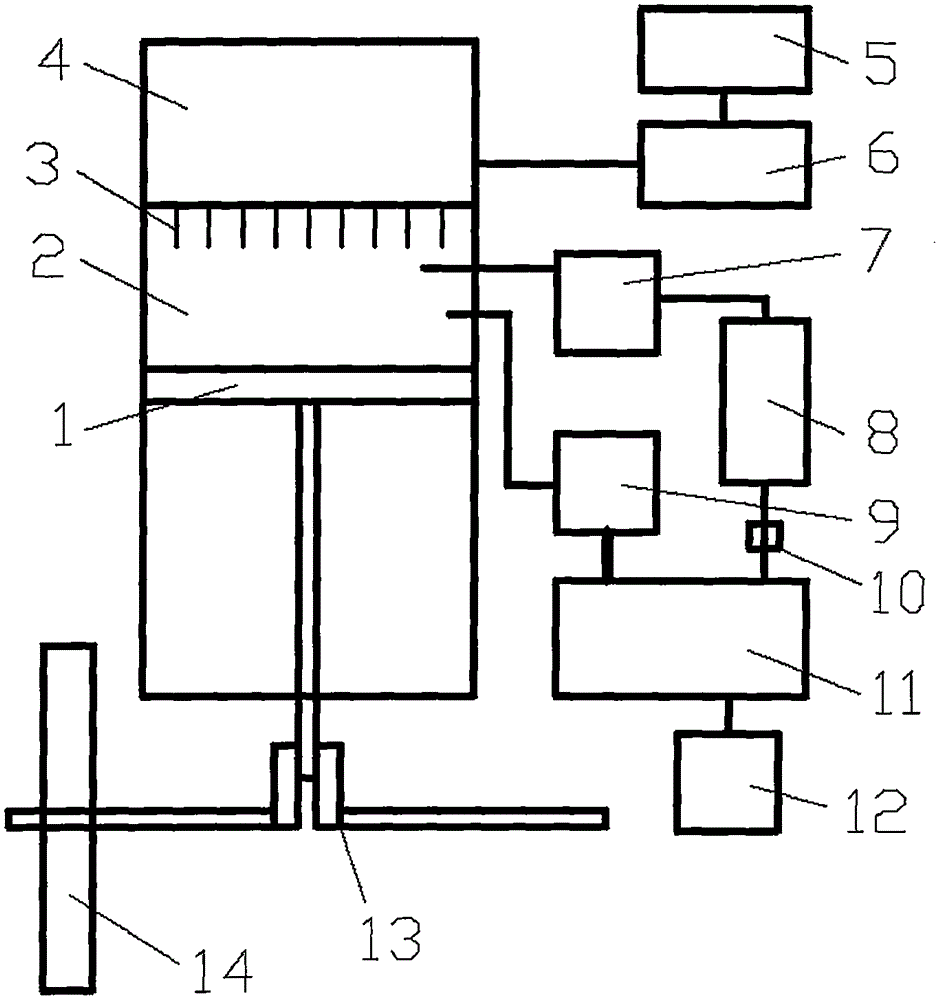
[0156] exist figure 1 Among them, the gas fusion fuel can be electrolytically produced by the heavy water storage electrolysis system (5) and then supplied to the gas storage tank system (6), and the gas fusion fuel enters the thermal resonance fusion reactor ( 4) A fusion reaction occurs in the interior, and the released heat energy is conducted to the heat exchanger of the heat exchanger system (3)...


PUM


Abstract

The invention provides a thermal resonance fusion engine, and belongs to the technical field of engines. The thermal resonance fusion engine comprises an internal expansion part, a Sterling engine, a steam piston, a steam turbine and a gas turbine; turbine air jetting, punching air jetting and a rocket type are achieved; gas and liquid working media, and an closed or opened cycle are adopted based on a thermal resonance fusion stack; a standardized, modularized and serial design is adopted; fossil fuel is not used and oxygen is not needed in an operation process; an operation mode that only fusion fuel is input and mechanical power and a pollution-free fusion product are output is realized, and long-period, safe, stable and economic operation is realized. A principle technology, industrial manufacturing and large-scale industrialization are all feasible. The structure is simple. No radiation is formed outside a shielding layer. A plurality of thermoelectricity and power sources can be provided at the same time. The thermal resonance fusion engine can be enlarged or miniaturized. The thermal resonance fusion engine can be used as a mini-size, small-size, middle-size or large-size engine for being widely applied to vehicles, ships and various machines. The thermal resonance fusion engine can be operated for ultra-long time. The thermal resonance fusion engine can provide green, safe, cheap and sufficient mechanical power to development of economic society and civilization, and is especially suitable for long-distance and long-time comprehensive application.

Description

technical field [0001] The invention relates to an engine, especially a thermal resonance fusion engine based on a thermal resonance fusion reactor, which can operate safely and stably for a long time under ordinary conditions and not too high temperature, and can be used as a micro, small, medium and large power plant. Background technique [0002] At present, there are many kinds of known engines. An engine is a device that converts other forms of energy into mechanical power. Including internal combustion engine, external combustion engine and electric motor etc. [0003] An internal combustion engine is a device that burns fuel inside the engine and converts the heat energy it releases directly into mechanical power. Internal combustion engines are used in a wide variety of applications. Including reciprocating, rotary and free piston internal combustion engines and rotary impeller gas engines. But the internal combustion engine usually refers to a piston internal co...

Claims


Application Information

Patent Timeline
IPC IPC(8): F02G1/043
CPCF02G1/043F02G1/0435
Inventor 董沛谷济源董保国
Owner 董沛
Learn More