Robust control system and method for electric time synchronization system
A time synchronization system and robust control technology, applied in time division multiplexing systems, electrical components, multiplexing communications, etc., can solve problems affecting the reliability of system time signals and lack of monitoring of internal devices in time synchronization systems , to achieve the effect of ensuring reliability, ensuring safety and reliability, and improving safety
- Summary
- Abstract
- Description
- Claims
- Application Information
AI Technical Summary
Problems solved by technology
Method used
Image
Examples
Embodiment 1
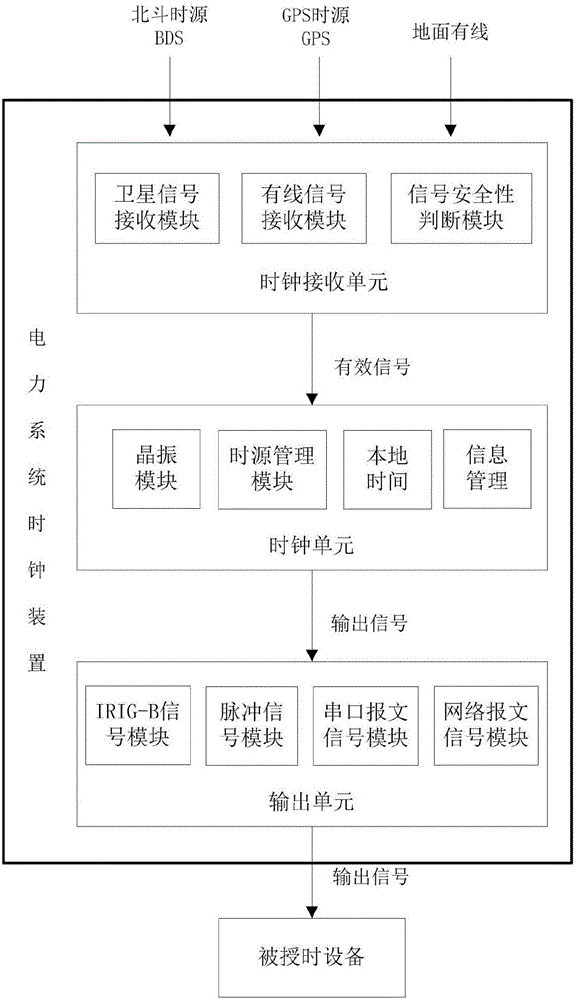
[0039] The present invention proposes a robust control system for a power time synchronization system and its implementation method. This method starts from the signal source of the time synchronization system, and by introducing multiple external time sources and judging the signal security of the input time source, Eliminate interference from external unstable signals or maliciously tampered input time source signals, so as to select the most reliable time source as the synchronization time source of the master clock device to ensure the reliability of the time source signal of the master clock device; on the other hand, through robust The control realizes the closed loop of the time synchronization system. The main clock device uses the optical port wavelength division multiplexing technology to monitor each device of the time synchronization system, and timely finds the clock device with abnormal time synchronization and adjusts it, so as to ensure the safety and reliability...
Embodiment 2
[0046] The present invention also provides a method for realizing the robust control system of the power time synchronization system. The closed-loop design and realization of the time synchronization system based on the robust control includes:
[0047] Step 1: A time synchronization system using dual master clock devices;
[0048] Step 2: The slave clock device receives safe and reliable signals, and the dual master clock devices receive external time source signals and complete synchronization;
[0049] Step 3: The master clock device monitors the output signals of each device in the time synchronization system to determine the faulty device;
[0050] Step 4: Determine the time offset of the output signal of the time synchronization system and the master clock device.
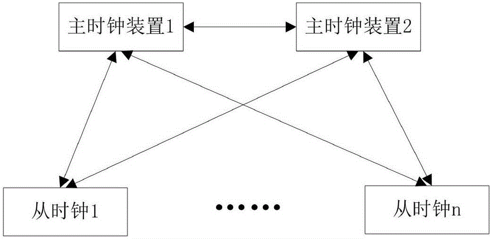
[0051] Master clock 1 and master clock 2 are connected to each other through optical fiber to obtain the time synchronization deviation, and synchronize information through the network. Master clock 1 and m...
Embodiment 3
[0059] Figure 4 It is a typical application example of the smart substation time synchronization system. The main clock 1 and the main clock 2 are mutually standby. The main clock 1 provides the time synchronization signal for the station control layer equipment, and the slave clock receives the IRIG-B signal output by the main clock 1 and the main clock 2. And after the synchronization is completed, it provides a time synchronization signal for the measurement and control device and the protection device.
[0060] The present invention can be applied to the design of the time synchronization system in the intelligent substation, and the application schematic diagram is as follows Figure 4shown. The master clock device is deployed at the station control layer, and adopts a dual master clock configuration, in which the master clock 1 is the master clock, and the master clock 2 is the backup clock, and the communication of the dual master clocks is realized by associating the...
PUM
 Abstract
Description
Claims
Application Information
 - R&D
- Intellectual Property
- Life Sciences
- Materials
- Tech Scout
- Unparalleled Data Quality
- Higher Quality Content
- 60% Fewer Hallucinations
Browse by: Latest US Patents, China's latest patents, Technical Efficacy Thesaurus, Application Domain, Technology Topic, Popular Technical Reports.
© 2025 PatSnap. All rights reserved.Legal|Privacy policy|Modern Slavery Act Transparency Statement|Sitemap|About US| Contact US: help@patsnap.com


