Ore lifting system, ore lifting control method and mining system for mining of metal nodules

A control method and technology for nodules, which are applied in the fields of mining minerals, special mining, and earth-moving drilling, etc., can solve the problems of impeller wear and nodules breakage, fragmentation, low mining efficiency and resource recovery rate, and easy entanglement of cables, so as to improve mining efficiency. , large particle size, reducing wear and damage

Inactive Publication Date: 2017-06-13
宋桂霞
View PDF5 Cites 4 Cited by
  • Summary
  • Abstract
  • Description
  • Claims
  • Application Information

AI Technical Summary

Problems solved by technology

Continuous chain bucket mining uses a winch to drive a rope chain with many buckets to continuously mine polymetallic nodules on the seabed to the workboat. However, this method has disadvantages such as low mining efficiency and resource recovery rate, and easy entanglement of cables.
Air-lift mining is to use high-pressure air to transport polymetallic nodules and muddy water from the seabed to the surface through the ore pipeline. It needs to be equipped with a large air volume and high air pressure air compressor, which has the disadvantages of low ore carrying speed, large energy consumption, Disadvantages such as high mining cost
The mortar pump hydraulic pipeline lifting method is to install the pump on the lifting pipeline and use the potential energy of seawater to lift it. Its advantages are simple process and high efficiency. However, the defect of this process is that the impeller wears and the nodules are broken by the nodules passing through the pump. and differentiation

Method used


Image

  • Ore lifting system, ore lifting control method and mining system for mining of metal nodules
  • Ore lifting system, ore lifting control method and mining system for mining of metal nodules

Examples


Embodiment Construction

[0017] The specific embodiments of the present invention will be further described below in conjunction with the accompanying drawings.

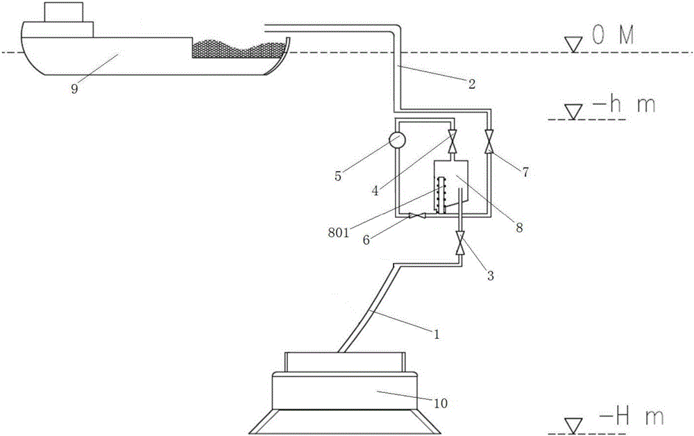
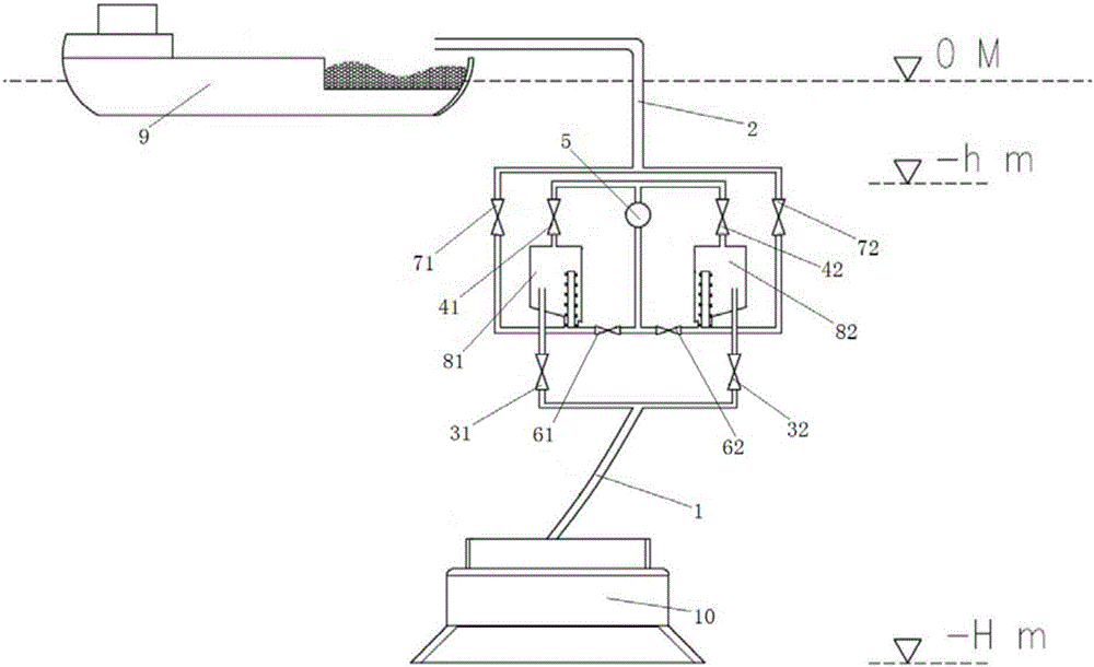
[0018] The present invention is realized like this, as figure 1 As shown, the ore lifting system for metal nodule mining includes ore suction hose 1, ore lifting hose 2, and an ore lifting drive assembly connected between ore suction hose 1 and ore lifting hose 2, which is characterized in that , the ore lifting drive assembly includes a submersible sewage pump 5 and a separator 8 located under the sea surface, the separator 8 communicates with the ore suction hose 1 through the ore suction control valve 3, and the separated water outlet at the top of the separator 8 is connected to the submerged sewage The water inlets of the pumps 5 are connected through the pumping control valve 4, and the nodule discharge outlet at the bottom of the separator 8 is connected with the water outlet of the submersible sewage pump 5 and the ore lifting hose 2...


PUM


Abstract

A mining lifting system, a mining lifting control method, and a mining system for mining metal nodules, wherein the mining lifting system includes an ore suction hose, an ore lifting hose, and a lifting hose connected between the ore suction hose and the ore lifting hose. Mine drive assembly, the mine lift drive assembly includes a submersible sewage pump and a separator located under the sea surface, the separator communicates with the ore suction hose through the ore suction control valve, the separated water outlet on the top of the separator and the water inlet of the submersible sewage pump The nodules outlet at the bottom of the separator communicates with the water outlet of the submersible sewage pump and the ore-lifting hose through the drainage control valve and the mine-lift control valve respectively; the mining system includes the above-mentioned structure for metal In the hoisting system for nodule mining, a mining ship is installed at the top of the hoisting hose, and a mining robot is connected to the bottom end of the ore suction hose. The invention satisfies the technical requirements of mining nodules with large particle size, durability and reliability, and continuous mining, realizes continuous operations of ore collection, ore suction, separation and ore lifting, and improves mining efficiency.

Description

technical field [0001] The invention relates to deep-sea nodule mining technology, in particular to a mining system for metal nodule mining, a mining control method and a mining system. Background technique [0002] At present, the methods for exploiting deep-sea resources in the world mainly include continuous chain bucket method, mortar pump hydraulic pipeline lifting method and air lifting method. Continuous chain bucket mining uses a winch to drive a rope chain with many buckets to continuously mine polymetallic nodules from the seabed to the workboat. However, this method has disadvantages such as low mining efficiency and resource recovery rate, and easy entanglement of cables. Air-lift mining is to use high-pressure air to transport polymetallic nodules and muddy water from the seabed to the surface through the ore pipeline. It needs to be equipped with a large air volume and high air pressure air compressor, which has the disadvantages of low ore carrying speed, larg...

Claims


Application Information

Patent Timeline
IPC IPC(8): E21C50/00
CPCE21C50/00
Inventor 宋桂霞
Owner 宋桂霞
Why Eureka
Try Eureka