In-site measuring method and device of cutter abrasion

A tool wear and measurement method technology, which is applied in the direction of measuring devices, optical devices, instruments, etc., can solve the problems of inability to guarantee the accuracy of detection results and many interference factors in detection, and achieve real-time active control, low cost, and improved workpiece quality. The effect of machining accuracy

Inactive Publication Date: 2017-06-13
HUBEI UNIV OF ARTS & SCI
View PDF6 Cites 43 Cited by
  • Summary
  • Abstract
  • Description
  • Claims
  • Application Information

AI Technical Summary

Problems solved by technology

Indirect measurement can detect the tool status in situ, but there are too many interference factors in the detection, and the accuracy of the detection results cannot be guaranteed

Method used


Image

  • In-site measuring method and device of cutter abrasion
  • In-site measuring method and device of cutter abrasion
  • In-site measuring method and device of cutter abrasion

Examples


Embodiment Construction

[0024] Below in conjunction with accompanying drawing, the present invention is described in further detail:

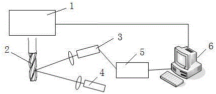
[0025] Measuring principle such as figure 1 shown. The tool 2 is installed on the tool holder on the main shaft of the CNC machine tool 1, and is driven by the tool holder to rotate with the main shaft during work. The CCD camera 3 and the line structure laser 4 are horizontally arranged on the side of the tool 2 , the CCD camera 3 is connected to the image acquisition card 5 , and the image acquisition card 5 is connected to the computer 6 . The line laser of the line structure laser 4 is projected vertically onto the cutting edge of the tool 2, and is modulated and deformed by the surface topography of the tool 2. The deformed laser line is imaged on the photosensitive surface of the CCD camera 3 placed at a certain angle to form a light strip image, image acquisition card 5. Transmit the light strip image to the computer 6; after image processing and calculation,...


PUM


Abstract

The invention discloses an in-site measuring method and device of cutter abrasion, and belongs to the technical field of the in-site measuring method and device of cutter abrasion. The method comprises the first step of installing a linear structure laser device and a CCD camera on the lateral of a cutter, wherein the CCD camera is connected to a computer through an image collecting card; the second step of making ray laser be vertically projected to the knife blade of the cutter, wherein deformed laser rays image on a photosensitive surface of the CCD camera and are then transmitted to the computer; the third step of obtaining a two-dimensional size of a ray bar point on a laser plane through image processing and calibration calculation; the fourth step of making the device rotate along with the cutter to scan the cutter for one round to obtain three-dimensional size data of the whole cutter; the fifth step of comparing the three-dimensional size data with a standard cutter three-dimensional model to obtain abrasion loss. The in-site measuring method and device of cutter abrasion have the advantages that the cost is low, the precision is high, the strip image information is easy to obtain, the practicability is high, the active control is achieved, the measuring precision at the micrometer level can be reached, and thus the measuring method and device of cutter abrasion are suitable for in-site measuring of cutter abrasion.

Description

technical field [0001] The invention belongs to the technical field of tool wear measurement methods and devices. In particular, the invention relates to an in-situ measurement method and device for the wear amount of a milling cutter of a numerical control milling machine or a machining center. Background technique [0002] The cutting tool is a tool for mechanical processing. When processing workpieces, wear and tear will inevitably occur. If the bluntness standard is exceeded, it will not only affect the accuracy of the workpiece, but also lead to waste products and affect the processing cost. [0003] On-site measurement of tool wear is a prerequisite for ensuring machining quality and efficiency. At present, the tool detection methods mainly include direct measurement method and indirect measurement method. Direct measurement of knives can identify changes in blade appearance, surface quality, or surface shape. The main methods are ray measurement, optical measurement...

Claims


Application Information

Patent Timeline
Patent Type & Authority Applications(China)
IPC IPC(8): G01B11/24
CPCG01B11/24
Inventor 王中任刘海生肖光润
Owner HUBEI UNIV OF ARTS & SCI
Why Eureka
Try Eureka