Phononic crystal structure and design method for ship vibration isolation

A phononic crystal and design method technology, applied in design optimization/simulation, calculation, special data processing applications, etc., can solve unavailable problems, achieve the effect of enhancing robustness, ensuring joint strength and process stability

Inactive Publication Date: 2017-06-13
CHINA SHIP DEV & DESIGN CENT
View PDF5 Cites 13 Cited by
  • Summary
  • Abstract
  • Description
  • Claims
  • Application Information

AI Technical Summary

Problems solved by technology

[0004] The vibration isolation structure used in actual naval engineering must not only have a certain amount of vibration isolation, but also meet the requirements of static strength, static stiffness, impact...

Method used


Image

  • Phononic crystal structure and design method for ship vibration isolation

Examples


Embodiment Construction

[0028] The embodiments of the present invention will now be described in conjunction with the accompanying drawings, and the present invention is not limited to the following embodiments.

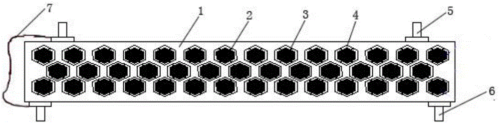
[0029] Such as figure 1 As shown, a phononic crystal structure used for ship vibration isolation includes a phononic crystal matrix 1, a spring 2 and a tungsten block 3. The phononic crystal matrix is ​​a periodically distributed honeycomb structure, and the springs are symmetrically arranged on the inner wall of the honeycomb 4 On the top, the tungsten block is set in the inner cavity of the honeycomb, and the outer wall is in contact with the top of the spring. The four corners of the top surface and the bottom surface of the phononic crystal substrate are respectively provided with an upper connection block 5 and a lower connection block 6. The upper and lower connection blocks are grounded Connected to line 7 to meet the grounding requirements of ship equipment. The phononic crystal ma...


PUM


Abstract

The invention relates to a phononic crystal structure and design method for ship vibration isolation. The structure comprises a phononic crystal base, a spring, and a tungsten slug, the phononic crystal base is of a honeycomb structure distributed periodically, the spring is symmetrically arranged on the inner wall of a honeycomb, the tungsten slug is arranged in a cavity in the inner portion of the honeycomb, the outer wall is abutted against the top of the spring, the top face and the four angles of the bottom face of the phononic crystal base are respectively connected with an upper link block and a lower link block, and the upper link block and the lower link block are connected with a ground wire. The phononic crystal structure and design method for ship vibration isolation use a local periodic resonance principle, have an elastic band wave gap, and increase the vibration isolation difference.

Description

technical field [0001] The invention belongs to the technical field of ship vibration isolation, and in particular relates to a phonon crystal structure and a design method for ship vibration isolation. Background technique [0002] As actual naval engineering has higher and higher requirements for radiation noise and cabin noise indicators, the traditional design based on the physical principle of positive equivalent mass density / positive equivalent stiffness Although vibration isolation structures such as trusses have a certain amount of vibration isolation in different frequency bands and can achieve a certain vibration reduction effect, the effective vibration isolation amount and vibration reduction effect are increasingly unable to meet the needs of actual naval engineering. [0003] The elastic wave bandgap refers to the specific frequency range in artificial elastic bodies where elastic waves are prevented from propagating. In 2000, Liu Zhengyou and others disclosed...

Claims


Application Information

Patent Timeline
IPC IPC(8): G06F17/50
CPCG06F30/15G06F30/23Y02T90/00
Inventor 刘志忠陈侯京张俊杰
Owner CHINA SHIP DEV & DESIGN CENT
Why Eureka
Try Eureka