Motor comprising HALBACH array and equipment comprising motor

An array and permanent magnet technology, applied in the direction of electric components, electrical components, electromechanical devices, etc., can solve the problems of permanent magnet damage, low torque density, complex processing, etc., and achieve the effect of reducing mass, reducing weight and improving torque density

Active Publication Date: 2017-06-13
NOVOMOTO LTD
View PDF9 Cites 16 Cited by
  • Summary
  • Abstract
  • Description
  • Claims
  • Application Information

AI Technical Summary

Problems solved by technology

[0002] At present, in the field of permanent magnet motors, a tooth and slot structure is usually used on the opposite surface of the stator and / or mover, and a single permanent magnet is placed in the slot, but the motor with this structure often has a small torque density. The development of robots requires motors that can achieve high torque density, but motors with this structure cannot meet the requirements
[0003] In order to achieve high torque density, people began to use HALBACH array permanent magnets again. HALBACH array permanent magnets superimpose and cancel each other through the magnetic field in the middle, so that the magnetic field strength on one side is enhanced, which in turn can increase the air gap magnetic density of the motor. Therefore, in The field of permanent magnet motors has been widely used, such as mentioned in the patent: CN203278585, such as Image 6 As shown, the rotor of the motor includes a HALBACH array arranged on the opposite surface of the rotor and the stator. The HALBACH array using this arrangement requires a plurality of permanent magnets with various magnetization directions to form together, so the processing is complicated and costly. High, and the arrangement of this array requires the permanent magnets in the middle to be close to each other, so the assembly is more troublesome, and it is easy to cause damage to the permanent magnets

Method used


Image

  • Motor comprising HALBACH array and equipment comprising motor
  • Motor comprising HALBACH array and equipment comprising motor
  • Motor comprising HALBACH array and equipment comprising motor

Examples


Embodiment 1

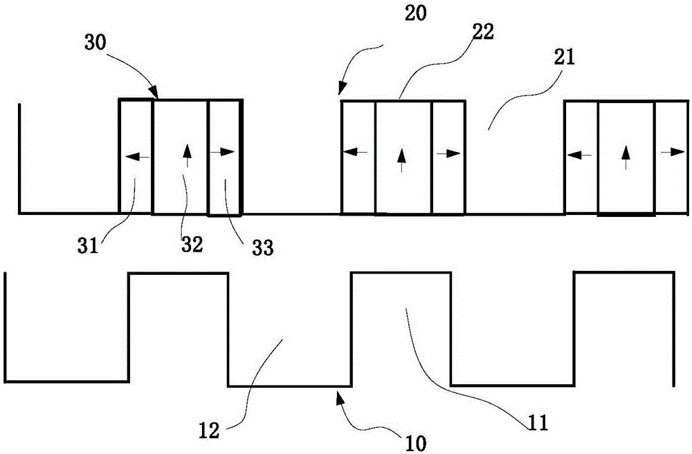
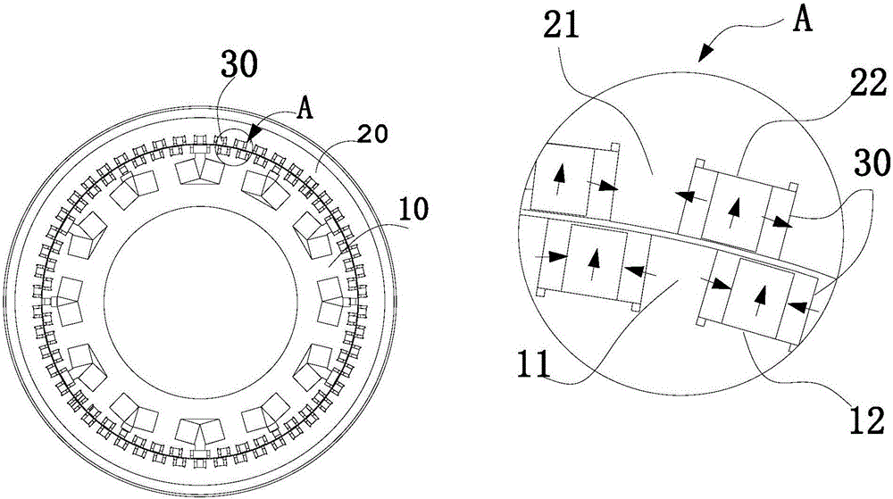
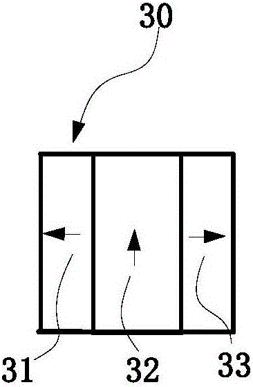
[0032] figure 1 A schematic diagram of a partial structure of a linear motor provided by an embodiment of the present invention; figure 2 It is a structural schematic diagram of a rotating electrical machine provided by an embodiment of the present invention, and the right side is an enlarged structural schematic diagram of part A.

[0033] In the field of permanent magnet motors, there are existing permanent magnet motors using HALBACH arrays. As described in the background, the opposing surfaces of the rotor and stator of the motor are surrounded by HALBACH arrays. The HALBACH array using this arrangement requires a plurality of permanent magnets with various magnetization directions to form together, and its processing is complicated, and the arrangement of this array requires the permanent magnets in the middle to be close to each other, so it is relatively difficult to assemble. Troublesome, and easy to cause damage to the permanent magnet.

[0034] Such as figure 1...

Embodiment 2

[0065] Embodiment 2 of the present invention also provides a device, which includes the motor described in Embodiment 1.

[0066] For the motor, refer to the description in Embodiment 1, which will not be repeated here.


PUM


Abstract

The invention provides a motor comprising an HALBACH array. The motor comprises stator and mover assemblies; a plurality of teeth and groove structures are formed in opposite surfaces of the stator and the mover; and the motor also comprises a plurality of HALBACH array permanent magnet units distributed in the multiple grooves of the stator and/or the mover. The invention also provides corresponding equipment. By adoption of the motor provided by the invention, the multiple HALBACH array permanent magnet units are defined in the grooves of the stator and/or the mover respectively to form the simple HALBACH array arrangement, so that the torque density of the motor can be improved while batch production of the permanent magnets can be facilitated, and production cost can be lowered; and in addition, the motor is convenient to install and the permanent magnets are not damaged easily.

Description

technical field [0001] The invention relates to the technical field of motors, in particular to a motor including a HALBACH array and equipment including the motor. Background technique [0002] At present, in the field of permanent magnet motors, a tooth and slot structure is usually used on the opposite surface of the stator and / or mover, and a single permanent magnet is placed in the slot, but the motor with this structure often has a small torque density. The development of robots requires motors that can achieve high torque density, but motors with this structure cannot meet the requirements. [0003] In order to achieve high torque density, people began to use HALBACH array permanent magnets again. HALBACH array permanent magnets superimpose and cancel each other through the magnetic field in the middle, so that the magnetic field strength on one side is enhanced, which in turn can increase the air gap magnetic density of the motor. Therefore, in The field of permanen...

Claims


Application Information

Patent Timeline
Patent Type & Authority Applications(China)
IPC IPC(8): H02K1/17H02K1/27
CPCH02K1/17H02K2213/03H02K1/2792H02K1/2783
Inventor 何国斌
Owner NOVOMOTO LTD
Why Eureka
Try Eureka