Electrodialyzer mounting unit, mounting method and electrodialyzer

An electrodialyser and installation unit technology, which is applied in the field of electrodialysis, can solve problems such as affecting the effect of electrodialysis, dead corners of clapboard water distribution tanks, assembly errors, etc., and achieves the effects of convenient assembly, prevention of dead ends, and reduction of resistance.

Pending Publication Date: 2017-06-20
浙江弗莱德环境科技股份有限公司
View PDF8 Cites 2 Cited by
  • Summary
  • Abstract
  • Description
  • Claims
  • Application Information

AI Technical Summary

Problems solved by technology

[0004] At first, the processing of the partition board adopts the method of bonding the two pieces after punching with a die, and now it is changed to injection molding. During the assembly process, the two kinds of separators and the anion and cation exchange membranes are stacked alternately, which is prone to assembly errors, and due to the design of the separators, the existing electrodialyzers are easy to There is a dead angle at the water distribution tank of the partition, which leads to scaling and affects the effect of electrodialysis

Method used


Image

  • Electrodialyzer mounting unit, mounting method and electrodialyzer
  • Electrodialyzer mounting unit, mounting method and electrodialyzer
  • Electrodialyzer mounting unit, mounting method and electrodialyzer

Examples


Embodiment 1

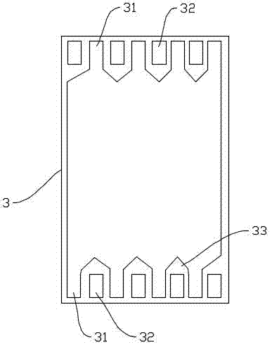
[0035] Such as image 3 and 4 Shown, when dividing plate A3 and dividing plate B4 are separate individuals, the installation method of the electrodialyzer provided by the present invention is as follows:

[0036] Step 1: The mesh cloth needs to be bonded to the surface of the separator body through a hot pressing process to form a separator. Step 2: Select a cation selective permeable membrane 21 that only allows cations to pass through, and set it on the electrode plate 1A Above, place partition A3 above the cation selective permeable membrane 21, then place an anion selective permeable membrane 22 that only allows anions to pass through above the partition A, and then place a partition on the anion selective permeable membrane 222 B4, then place the cation selective permeable membrane 21 on the separator B4, and repeat this several times, step 3: place the electrode plate 1B above the cation selective permeable membrane 21, and place the cation selective permeable membrane ...

Embodiment 2

[0039] Such as Figure 5 As shown, the edge of the partition A3 and the partition B4 fit together to form a whole, that is, when the two are formed on the same raw material, the installation method of the electrodialyzer provided by the present invention is as follows:

[0040] Step 1: Firstly, the mesh cloth is bonded to the surface of the partition body by hot pressing process to form a partition for use; Step 2: Fold the partition A3 and the partition B4 first, so that the partition A3 is located on the partition The lower surface of B4, then the cation selective permeable membrane 21 is placed on the electrode plate 1A, and the folded separator A3 and separator B4 are placed on the cation selective permeable membrane 21. At this time, the separator A3 and the cation The permselective membrane 21 is handed over, and then the anion permselective membrane 22 is placed in the interlayer of the separator A3 and the separator B4, and then the cation permselective membrane 21 is ...


PUM


Abstract

The invention discloses an electrodialyzer which comprises at least one mounting unit; the mounting unit is composed of electrode plates, an ion selective permeability membrane arranged between the electrode plates and a baffle plate used for supporting the ion selective permeability membrane. Meanwhile, the invention also provides a mounting method of the electrodialyzer. According to the mounting method, the desalting effect of the electrodialyzer to salt water can be remarkably improved, the phenomenon that a dead corner appears in the electrodialyzer to cause dead water and scaling are prevented, separation of anions and cations in a fresh water chamber is guaranteed, and the quality of fresh water is improved.

Description

technical field [0001] The invention relates to the field of electrodialysis, in particular to an electrodialyzer installation unit, an installation method and an electrodialyzer. Background technique [0002] Under the action of a direct current electric field, electrodialysis (electrodialysis, ED) technology is driven by potential difference, so that ions in the solution can selectively pass through the ion exchange membrane, so as to realize the concentration or desalination of the salt solution and the refining or purification of the salt. It has been widely used in seawater desalination, wastewater treatment, food refining, acid-base purification and other fields in the technical industry. [0003] The electrodialyzer is mainly composed of anion exchange membrane, cation exchange membrane, separator, protective frame, electrode, water guide plate and locking device, etc. According to the flow channel structure of the separator, it can be divided into non-loop type and l...

Claims


Application Information

Patent Timeline
Patent Type & Authority Applications(China)
IPC IPC(8): B01D61/46B01D61/52
CPCB01D61/422B01D61/46B01D61/52B01D2311/2684B01D2311/2623
Inventor 徐陆培
Owner 浙江弗莱德环境科技股份有限公司
Why Eureka
Try Eureka